The electric motor of the heater fan (“stove”) on VAZ 2108, 2109, 21099 cars and their modifications is a commutator, DC motor with excitation from permanent magnets. Has three rotation speeds. The speed is selected by a four-position switch on the instrument panel. Below are the electrical diagrams for connecting it.
Wiring diagram for the electric motor fan (“stove”) of VAZ 2108, 2109, 21099 cars with a “low” instrument panel and mounting block 17.3722
Wiring diagram for the electric motor fan (“stove”) of VAZ 2108, 2109, 21099 cars with a “high” instrument panel and mounting block 2114
Notes and additions
— The fan electric motor can be connected to the on-board network either directly (highest speed) or through an additional resistor having two resistance spirals (0.23 Ohm and 0.82 Ohm). If both spirals are included in the chain, the speed is low, if one is 0.23, the speed is average.
More articles on electrical equipment of VAZ 2108, 2109, 21099 cars
Schematic electrical diagrams, connecting devices and pinouts of connectors
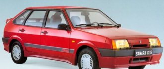
The VAZ-2109 car was produced at AvtoVAZ from 1987 to 1997. Years of production 21099: 1990-2004 - in Russia, 2004-2011 - in Ukraine. Here are colored wiring diagrams (for the injector and carburetor) with a description of all the elements for various modifications. The information is intended for self-repair of cars. Electrical circuits are divided into several blocks for ease of viewing via a computer or smartphone; there are also circuits in the form of a single picture with a description of the elements - for printing on a printer.
Like the entire car, its electrical equipment was at an average level, so owners of Nines should know the wiring diagram thoroughly for routine repairs with their own hands.
Modifications of VAZ-2109
VAZ-2109 . The basic model, which was produced from 1987 to 1997, was equipped with a 1.3-liter VAZ-2108 carburetor engine with a capacity of 64 horsepower.
VAZ-21091 . Modification of a car with a derated VAZ-21081 engine, 1.1 liter and 54 horsepower. It was mass-produced from 1987 to 1997.
VAZ-21093 . Modification of a car with a VAZ-21083 carburetor engine, 1.5 liters and 73.4 horsepower. Serially produced from 1988 to 2006.
VAZ-21093i . Modification with a VAZ-2111-80 injection engine, 1.5 liters. the first prototype appeared in 1994, mass production began in November 1998.
VAZ 21093-22 . Model made specifically for the Finnish market. It features improved interior trim, pre-installed alloy wheels and a new dashboard. The car was equipped with a 1.5 liter injection engine. Produced from 1995 to 1998.
VAZ-210934 .
An all-wheel drive SUV with a VAZ-21093 body mounted on a Niva frame, on which the suspension, steering, engine, gearbox and transfer case from the same VAZ-2121 Niva model were already installed.
Design of the VAZ-21099 heater
And then everything is simple: the created flow passes through the radiator honeycombs, where heat exchange occurs, as a result, heat is transferred to the air, which then blows into the required zones through the air ducts.
The design of the VAZ-21099 stove includes several main components:
- stove body made of plastic;
- heating system radiator (connected to the cooling system);
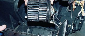
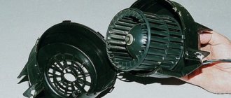
- electric fan;
- air ducts;
- heater control mechanism.
This car used heaters of two modifications (old and new), which were slightly different in design, but their components were completely identical.
Housing, radiator, dampers
Thanks to the housing, the required redirection of heating is ensured, since the movement created by the fan motor is immediately fed into it, rather than being dissipated. The body of the VAZ 2109 stove itself consists of two halves, connected to each other with special brackets. To reduce flow losses, a seal is placed between its halves. Partitions are made inside both halves, which provide the correct direction.
There is also a niche inside this case into which the radiator is installed. Initially, the radiator was made of brass, but now it is almost always made of aluminum. The design of the stove radiator 2109 is identical to the main one (consists of two tanks, tubes through which coolant circulates, and plates that form honeycombs), but is significantly smaller in size.
Video: The stove in the VAZ 2108, 2109, 21099, 2110, 2111, 2112, 2113, 2114, 2115 HEATS poorly
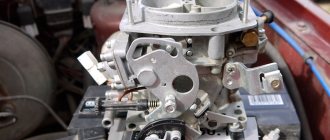
Wiring diagram for VAZ-2109 carburetor
- Headlight.
- Electric motor for headlight glass cleaning system. An optional part, used mainly on export vehicles.
- Limit switch for powering the engine compartment lamp.
- Klaxon.
- An electric motor drives a fan installed on the radiator of the cooling system.
- Temperature indicator that provides a control signal for the electric drive of the fan impeller.
- Alternator.
- Fluid supply valve for headlight glasses. Used in conjunction with paragraph 2.
- Fluid supply valve for the glass of the fifth door.
- Fluid supply valve to the front glass.
- Spark plugs.
- Hall sensor used to distribute ignition pulses.
- Coil.
- Limit switch for reverse gear lights.
- Fluid temperature meter in the cooling system.
- Starter.
- Accumulator battery.
- A sensor that measures the fluid level in the brake booster.
- Switch that controls the ignition system.
- Sensor for determining the position of the top dead center of the piston of the first cylinder. Installed on some export VAZ 2109 with a diagnostic system. Found only on cars before 1995.
- Diagnostic block. Optional element, installed together with item 20.
- Controller for controlling the solenoid valve installed in the carburetor.
- Starter switch contact block.
- Limit switch on the carburetor.
- Economizer valve.
- Sensor signaling an emergency decrease in oil pressure.
- Washer pump drive.
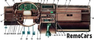
- Fan impeller motor for ventilation and heating systems.
- Resistance providing additional fan speeds.
- Speed shifter.
- Windshield wiper drive.
- Cigarette lighter.
- Illumination system for levers for adjusting heater operating parameters.
- Socket for additional equipment.
- Lamp for auxiliary lighting of the engine compartment.
- Illumination system for the glove box on the instrument panel.
- Relay and fuse link mounting block.
- Instrument panel light switch.
- Parking brake lamp limit switch.
- Brake lamp limit switch.
- Steering column switch lever block.
- Exterior lamp switch.
- Hazard switch.
- Turn on the rear fog lamp.
- Bimetallic fog lamp fuse.
- Heated glass switch on the fifth door.
- Turn signal repeaters on the front fenders.
- Central interior lighting.
- Individual lampshade.
- Switches for backlight operation on the middle pillars.
- Ignition switching unit.
- Egnition lock.
- “Low” type instrument cluster.
- Choke limit switch on the carburetor.
- Rear lights.
- Fuel level meter in the tank.
- Heated glass.
- Rear wiper drive.
- Two lamps for room illumination.
Internal structure and principle of operation
The heating system installed on the VAZ-2109 has its own differences and features compared to other cars in the AvtoVAZ line.
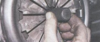
The heater consists of a pair of plastic casings (on the right and on the left), which are connected to each other along the entire perimeter with clamping brackets. A special flagellum is placed in the grooves of the casings to seal it well. The fan supplies air flow to the interior of the machine. The VAZ-2109 stove is designed so that the fan can be easily removed independently from the engine compartment.
An electric motor of type 45.37230 is attached to the casing, and a fan is located on its shaft. To obtain its desired rotation speed, additional resistance was provided. It was attached to the left side of the hole in the heater casing using a screw.
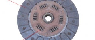
Heating system radiator
A radiator is built into the stove body to heat the air flows, which then blow into the cabin. Using three screws, this element of the system is screwed to the right casing and sealed with a polyurethane foam gasket.
The radiator design is a combination of:
- 2 rows of tubes.
- 2 rows of cooling plates.
- 2 plastic tanks.
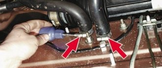
It has two pairs of pipes, it is connected to the cooling system by rubber pipes, where coolant circulation is ensured using a pump. In the valve casing, on the axis of the supply line, there is a plate valve, which has a hole; it allows the coolant to pass through. The valve lever is connected by a rod to the handle lever, which also controls the process of heating the air flow. If you turn this lever, the hole in the valve will open the line for coolant to enter the radiator.
Equipment diagram for VAZ-2109 injector
The VAZ 2109 wiring for the injector has many connectors for connecting sensors to the computer.
- TPS (throttle position sensor);
- DPKV (crankshaft position sensor);
- DT (temperature sensor);
- DSA (vehicle speed sensor);
- Canister purge valve;
- MAF (mass air flow sensor);
- DD (knock sensor) and others.
The weak point of the harnesses is the power wiring on the bottom shelf of the radiator, which is constantly exposed to high temperatures and in this place it is in no way protected from water and dirt. Another problem is a harness under the carpet next to the driver's seat. Moisture constantly accumulates there, and in order to remove it, you need to dry the floor, inevitably tugging on the rope.
Since the mid-90s, VAZ 2109 began to use engines with an injection system, which greatly changed the electrical layout of the engine compartment and instrument panel. Below is an electrical diagram of a 1999 car with an ECM type GM ISFI-2S and January 4/4.1.
- 1 - nozzle system;
- 2 - candles;
- 3 — ignition control module;
- 4 — diagnostic connector;
- 5 — General Motors or January controller;
- 6 — connector for connecting the instrument cluster;
- 7 — main relay of the system;
- 8 — fuse for power supply wiring of the controller and ignition system module;
- 9 — protection of the speed sensor and air flow meter circuits;
- 10 — fuel supply pump power protection;
- 11 — fuel pump controller;
- 12 — engine temperature meter;
- 13 — idle system;
- 14 — detonation meter;
- 15 — tank purge system for collecting fuel vapors;
- 16 — crankshaft position meter;
- 17 — speed meter;
- 18 — air flow meter;
- 19 — lambda probe;
- 20 — throttle position angle meter;
- 21 — electric fuel pump complete with fuel level sensor;
- 22 — connection of the ignition system;
- 23 — control lamp;
- 24 — ignition switch;
- 25 - switching block;
- 26 — radiator cooling fan.
Since 2002, all VAZ 2109 began to be equipped only with engines with an injection system. The diagram shows the electrical wiring harness for the Bosch MP7.0 ECM (Euro 2 standards) on a 2003 car with a VAZ 2111 engine.
- 1 — four nozzles;
- 2 — spark plugs 2109;
- 3 — ignition distribution module;
- 4 - diagnostic connector, led into the car interior;
- 5 — Bosch controller connector;
- 6 — connector for the combination of lamps and instruments;
- 7 - main switching device of the system;
- 8 — fuse-link of the main device;
- 9 — controller for controlling the parameters of the fan on the cooling radiator;
- 10 — fan controller fuse;
- 11 — fuel pump control relay;
- 12 — fuel pump wiring fuse;
- 13 — intake air flow sensor;
- 14 — throttle opening angle sensor;
- 15 — engine temperature meter;
- 16 — regulator of idle speed parameters;
- 17 — sensor for measuring detonation in cylinders;
- 18 — crankshaft position sensor;
- 19 — lambda probe;
- 20 — immobilizer control unit;
- 21 — immobilizer status indicator;
- 22 — speed sensor;
- 23 - electric motor for driving the fuel pump; in the same module there is a device for measuring the remaining fuel in the tank;
- 24 — purge valve for the gasoline vapor recovery system;
- 25 — connector of the ignition system braid;
- 26 — instrument cluster with Check Engine indicator and warning lamp;
- 27 — ignition system start relay;
- 28 - lock;
- 29 — installation and switching block;
- 30 - cooling system fan.
Where can the engine mass be located?
In almost 100% of modern cars, the body is used as a single source of electrical energy. The car body is like a universal wire with a negative charge for all consumers of electricity. That is why the body is called the painfully familiar term “mass”. Why “painfully familiar”? Yes, because if somewhere the contact with the mass is either poorly secured or oxidized, the inexplicable begins.
Let’s take the first example we come across: the sore subject of the first and second Samaras is the blinking of yellow and red headlights, etc. I have already analyzed this situation in the article: why the headlights do not light up, where I made a “mass”, as the main reason for unstable operation. But the headlights are a small thing compared to the performance of the engine and the electronic engine control system (ECS). In this article we will look at the weak “mass” points on the VAZ 2114 2113 2115 with 1.5l, 1.6l engines.
Battery weight
The “minus” on the battery has two branches: a thick wire and a thin one. A thick wire runs from the battery negative to the engine housing. If this contact is not secured properly, then the battery is not fully charged, the starter does not develop full power, and the ECM stalls (since it takes weight from the engine).
On the negative mount of the battery with the engine, you need to check the tightness of the two nuts between which the contact to the engine is attached: first of all, loosen the outer nut and tighten the inner one, and then tighten the outer one.
The second wire from the battery is much thinner and is attached to the body next to the battery itself. This wire is the source for all energy consumers in the car. Here you also need to check the tightening torque of the nut both to the body and to the battery terminal.
ECM weight
For SAMAR with a 1.5 liter engine, the mass for the ECM is taken from the engine housing, from the fastening of the plugs . The plugs are located on the right side of the block head.
For SAMAR with a 1.6 liter engine, but also 1.5 liter engines, which have a new generation ECM (Bosch 7.9.7, January 7.2), the weight of the ECM is taken from a welded stud. The pin is attached to the metal frame of the instrument panel to the floor tunnel (under the ashtray). In practice, it happens that this pin is painted at the factory and is loosely tightened. Therefore, over time it may become loose and at the moment the fan is turned on, there will be a drop in the voltage of the following sensors (which will lead to jumps in speed): DTOZH, TPS, MAF.
Weight of torpedo (instrument panel)
At this point in the bundle there are connections for the torpedo harness, circuit diagrams for the mounting relay and fuses, and the rear harness. This connection is located under the steering shaft mount. If this connection is unreliable, then deviations in the instrument panel readings are possible when energy consumers (headlights, turn signals, etc.) are turned on.
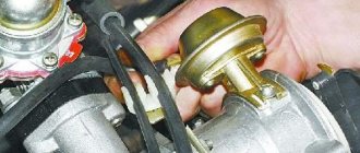
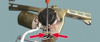
Heater motor weight
This ground connection is located under the instrument panel on the left side of the heater housing.
In conclusion, it is worth noting that absolutely all factory-made studs are not treated in any way other than paint, so over time, corrosion, oxidation appears, and voltage drops begin.
Relay and fuse box diagram 2109
The fuse blocks do not depend on the fuel injection system used - carburetor or injector. BP will differ only by year of manufacture of the car. That is, the mounting blocks for the carburetor and injector are the same. The VAZ 2109-099 fuse box (carburetor, injector) is located under the hood, in the compartment in front of the windshield on the left side.
Fuse block 2114-3722010-18
K1-relay for turning on headlight cleaners; K2-relay-breaker for direction indicators and hazard warning lights; K3 - windshield wiper relay; K4-relay for monitoring the health of lamps; K5-power window relay; K6 - relay for turning on sound signals; K7-relay for turning on the electric heating of the rear window; K8-relay for high beam headlights; K9-relay for low beam headlights; F1-F16 - fuses.
Fuse block 2114-3722010-60
K1 - Headlight wiper relay, K2 - Turn signal and hazard warning relay, K3 - Windshield wiper relay, K4 - Brake light and parking light relay, K5 - Power window relay, K6 - Horn relay , K7 - Rear window heating relay, K8 - Headlight high beam relay, K9 - Headlight low beam relay, F1 - F16 - Fuses, F1 - F20 - Spare fuses.
Attention! The power terminals on the generator often become loose, heat up, spark and melt the wiring. Pay attention to this point when searching for possible faults yourself.
Electrical diagram - wiring of a VAZ 2109 car with a carburetor engine and a low instrument panel (torpedo).
A - the order of conditional numbering of plugs in the ignition switch block of VAZ 2109 electrical equipment. B - the order of conditional numbering of the plugs in the block of the electric motor of the windshield wiper of the VAZ 2109.
Picture of the VAZ 2109 electrical circuit:
Table of decoding of the VAZ 2109 electrical circuit: