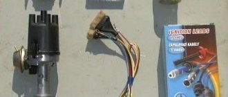
Components of the ignition system of the VAZ 2106
Previously, a distributor of the R-125B brand was installed on the car. This unit was mounted on the machine together with a carburetor marked 2103. The distributor had a special mechanical corrector in its design, and there was no vacuum regulator. The VAZ 2106 is equipped with spark plugs of type A17DV or plugs that have similar technical characteristics.
The design of the automotive system uses a VK347 type lock, equipped with an anti-theft device. The car uses a B117-A type ignition coil, which has an open magnetic circuit and is oil-filled and sealed.
The VAZ 2106 ignition is contact-based, but it is worth noting that sometimes there is also a contactless version of the system. The contact system is considered simpler in its design. VAZ contact ignition requires regular maintenance and monitoring of the condition of the contacts.
About the drive mechanism
To transmit torque to the distributor shaft on the “six”, a helical gear is used, rotated by a timing chain (in common parlance – “hog”). Since the element is located horizontally and the distributor roller is vertical, there is an intermediary between them - the so-called fungus with oblique teeth and internal slots. This gear simultaneously turns 2 shafts - the oil pump and the distributor.
Find out more about the timing chain drive design: https://bumper.guru/klassicheskie-modeli-vaz/grm/kak-vystavit-metki-grm-na-vaz-2106.html
The distributor drive consists of two transmission gears with oblique teeth
Both transmission links - the “hog” and the “fungus” - are designed for a long service life and are replaced during engine overhauls. The first part is removed after disassembling the timing chain drive, the second is pulled out through the upper hole in the cylinder block.
The VAZ 2106 distributor, equipped with a contact breaker, is a rather complex unit consisting of many small parts. Hence the unreliability of operation and constant failures of the spark generation system. The non-contact version of the distributor creates problems much less frequently, but in terms of performance characteristics it still falls short of modern ignition modules, which have no moving parts.
Ignition coil and other elements
It is somewhat different in the contactless system from the one used in the classical one. The reason is the different value of the secondary voltage. Thus, when operating an internal combustion engine with a contact (including contact-transistor) ignition system, 25-30 thousand volts are required to form a spark gap. But in a non-contact system you need to generate over 30 kV, sometimes even up to 40 kV. Therefore, more turns are needed in the secondary winding.
The remaining elements are completely similar for all three designs discussed above. You choose the armored wires connecting all high-voltage circuits yourself. They can be either in a silicone or rubber shell. Contactless ignition 2107 can work with any high-voltage wires recommended by the manufacturer. Candles must be used those recommended by the manufacturer. In this case, you can again choose the brand yourself.
What benefits can you get?
But you will get many benefits if you install an electronic ignition on the VAZ-2106 instead of a contact one. It’s better to start with the fact that any driver likes to drive more than to repair the car. But frequent replacement of the contact group or its cleaning and adjustment causes terrible hostility among motorists. Moreover, the contact can fail at any time, so you need to have a spare one with you. But the electronic system on this side is much more reliable and does not require frequent maintenance.
But the most important thing happens in the engine - the very heart of any car. His work is returning to normal. It begins to function correctly, regardless of the rotation speed. Whether at idle or at 4000 rpm, the engine runs perfectly smoothly, stably, and the air-fuel mixture ignites in a timely manner. And this improves your comfort, increases engine reliability, and most importantly, increases its service life.
Removal and installation of the ignition distributor of the VAZ 2106 distributor
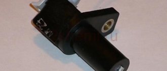
The ignition distributor (distributor) is removed from the VAZ 2106 car for repair or replacement. The engine of the VAZ 2106 model has a distributor of type 30.3706.
To distinguish it from distributors of other models, a mark (ring groove) is made on the shank. To remove the distributor from a VAZ 2106 car you will need: a spark plug wrench, a bit, two “7” keys, a “13” wrench, and a screwdriver. 1. Remove the tip from the spark plug of the first cylinder and unscrew it.
2. Close the spark plug hole with your finger.
3. Turn the crankshaft until the compression stroke begins in the 1st cylinder (air will begin to escape through the spark plug hole). Then, while continuing to turn the crankshaft, align mark d on the crankshaft pulley (highlighted with chalk) with the middle mark b (if you are using gasoline with an octane rating of 92 or 95) or the extended mark c (if you are using gasoline with an octane rating lower than 92). Reinstall the spark plug of cylinder 1 and connect the high-voltage wire to it.
4. Disconnect the hose from the vacuum ignition timing regulator. 5. Remove the high-voltage wires from the sockets of the distributor cover.
6. Unscrew the nut securing the distributor, remove the spring washer and plate. 7. Remove the distributor from the engine.
8. Turn over the distributor and, holding the lower nut, unscrew the nut securing the low voltage wire; remove the washer and wire. 9. Unfasten the holders and remove the cover from the new distributor.
WARNING
Before installing a new distributor on a VAZ 2106 car, check and, if necessary, adjust the gap between the contacts of the breaker.
10. Install high-voltage wires into the cover of the new distributor in accordance with the operating order of the engine cylinders.
NOTESThe operating order of the engine cylinders is: 1-3-4-2. The distributor rotor rotates clockwise. Cylinder numbers are marked on the distributor cap and on the engine cylinder head.
11. Connect the low-voltage wire to the new distributor.
12. Turn the rotor of the new distributor to a position in which its outer contact (shown by the arrow) will be directed towards the contact of the 1st cylinder on the distributor cover. NOTE
When the outer contact 2 of the rotor coincides with mark a on the cover, it simultaneously coincides with the head of screw 1 on the distributor body.
13. While holding the distributor shaft from turning, insert it into the socket on the cylinder block so...
14... so that the line passing through the spring latches is approximately parallel to the axis of the motor. 15. Secure the distributor in this position to the cylinder block without completely tightening the nut. Connect the hose to the vacuum regulator. 16. After installing the distributor on a VAZ 2106 car, check and, if necessary, adjust the ignition timing (see “Checking and adjusting the ignition timing”).
Operating principle of the distributor
In many ways, the operating principle of the distributor remained unchanged for many years. In VAZ cars, such as VAZ 2109, 2106, 2107, 2108, an ignition system of this type was used almost until the end of the last century.
The basis of the work is the connection of the distributor with the engine crankshaft. When the piston in the first cylinder takes the position corresponding to TDC, the breaker contacts open, a high voltage appears in the ignition coil, directed through a slider located in the distributor cover to the spark plug of the first cylinder.
There the combustion of the fuel assembly occurs, and the crankshaft continues to rotate. In addition to moving the pistons, it causes the breaker cam to rotate. When in another cylinder another piston occupies a position corresponding to TDC, at this moment the breaker contacts in the distributor open again, and a high-voltage voltage is generated in the ignition coil and supplied to the desired spark plug.
This joint rotation of the crankshaft, the breaker cam and the distributor slider ensures that a spark appears where and when needed. However, this does not cover all aspects of how the distributor works. To understand its operation, it is necessary to touch upon such concepts as the angle of the closed state of contacts (UZSK) and the ignition timing angle (IAF)
UZSK
A concept such as UZSK characterizes the time when the breaker contacts are closed. In essence, this is an indirect characteristic of the accumulation of energy in the coil after the completion of spark formation. UZSK directly affects the amount of energy spent on sparking and, accordingly, on engine operation.
In cases where the distance between the contacts is small, the coil will not accumulate the necessary energy and the spark energy will be low, which will lead to interruptions in the operation of the motor. A large gap also leads to interruptions, since the contact breaking time is reduced and the coil does not have time to fully discharge.
Each ignition system has its own optimal UZSK, to ensure which, if necessary, the distributor must be checked and adjusted.
UOZ
This concept concerns the moment of ignition of a fuel assembly. The fact is that its combustion does not occur instantly, and often, to ensure optimal conditions for such a process, it must begin earlier than the piston reaches the TDC position. The OZ characterizes the time by which the appearance of a spark precedes the appearance of the piston in the TDC position.
It is constantly changing, and its value completely depends on the operation of the motor under specific conditions, i.e. depending on the load, vehicle speed, quality and type of fuel used. To ensure optimal combustion of the fuel assembly, the distributor contains a centrifugal regulator and is also connected to a vacuum regulator.
DETAILS ABOUT THE MOST IMPORTANT ELEMENTS OF THE TRAMBER DEVICE
VACUUM REGULATOR
It is this device that can change the OZ if necessary. As soon as the motor load changes, appropriate adjustments are made to the operation of the distributor device parts.
Important! The load is determined using the throttle valve.
The vacuum regulator of the distributor is a closed cavity. To ensure better performance, the design is divided by a diaphragm. One cavity goes directly to the carburetor.
When a vacuum occurs, the diaphragm begins to move. As a result, pressure is exerted on the movable disk and the breaker cam. The response time of the latter is adjusted depending on the current situation.
Attention! The distributor changes the moment of spark formation, thereby affecting the performance characteristics of the motor.
OCTANE-CORRECTOR
This is a very important element in the distributor design. Without it, the entire system could not function normally. The unit changes the SOP depending on the fuel that is currently being used.
By its design, this distributor element resembles two plates with an arrow. The same arrow is installed on the engine. There are special lines on it, through which the ignition angle is adjusted. It is almost impossible to do without this part when refueling different types of gasoline.
CONTACTLESS SYSTEMS
Technologies do not stand still. Every year, the automotive world is rocked by new innovations. This is precisely what innovation became in its time, supplementing the distributor design with switches.
Attention! In switches, the signal is supplied to the control electronic module, and not to the coil.
The second name for non-contact systems in the distributor device is Hall sensors. The simple design of these devices ensures uninterrupted signal supply. The sensors themselves work due to changes in the magnetic field.
DIY installation and connection diagram
So, having made your choice, we suggest that you familiarize yourself with the necessary tools, the replacement procedure and video instructions.
Tool
From the tool you will need:
- Key 13 - remove and install distributor
- Screwdriver - tighten the screws.
- Drill with a metal drill, diameter for self-tapping screws
- Two self-tapping screws - screw the switch.
- Keys for 10 and 8 - remove and install the coil.
How to install step by step
- Disconnect the negative battery. Before starting work on the ignition system, disconnect the negative terminal of the battery
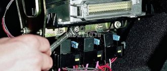
- Remove the distributor cover with high-voltage wires. Removing the ignition distributor cover
- Disconnect the high-voltage wire on the coil. Disconnecting the wire from the ignition coil
- Using short turns of the starter, set the ignition distributor slider perpendicular to the engine. This is how the distributor should be installed relative to the engine
- Mark the position of the distributor with a marker on the engine. Installing the ignition distributor slider
- Unscrew the nut holding the distributor using a 13mm wrench. Disconnect the wire connecting the device to the coil. Before removing the ignition distributor, disconnect the wire that goes to it from the coil
- Insert the new ignition distributor into the engine by removing the cover. The ignition distributor must be inserted into the standard socket
- Turn the distributor body so that the middle mark on it coincides with the mark you previously placed on the motor.
- Tighten the nut securing the new ignition distributor. The nut holds the ignition distributor in place
- Put on the distributor cover and connect the wires to it. This is how the cover is installed on the distributor
- Replace the ignition coil with a new one. A new system requires a new coil
- Connect the original and new wires to the coil. To connect everything correctly, use the diagram. All connections must match the diagram
- Install the switch in any convenient location. Drill holes and screw screws into them to hold the device. Check the connections of all VAZ-2106 systems. The switch will not take up much space under the hood and its location does not matter
- Start the engine. If it doesn’t start the first time, you can turn the distributor a little. This will change the ignition timing.
Contact ignition VAZ 2106
In the photo - VAZ 2106, which is an exact copy of the Fiat 124
Different ignition systems were installed on the car at different times, but the Fiat contact design is considered a classic. Its device is incredibly simple - an ignition coil, a distributor, a bundle of high-voltage wires and the right spark plugs. This is all that is needed for the correct operation of the engine. On the first batches of sixes, until 1980, a P125-B distributor of the simplest design without vacuum adjustment of the ignition timing was installed. After installing the standard Ozone carburetor, it became possible to equip the distributor with a vacuum advance angle adjustment system.
Structurally, distributors differ only in the presence of a vacuum membrane chamber, which is connected to the primary chamber of the carburetor. At a certain period, a distributor was installed without a vacuum chamber and it was structurally similar to the old one. Reel B117-a, sealed, filled with oil, with open magnetic conductors. In short, there is practically nothing to break. All that remains is to check the condition of the system elements and you can begin adjusting.
Replacing the VAZ 2106 distributor with your own handsAutoRemka
Distributor malfunctions lead to malfunctions in the ignition system. You can guess that the distributor is faulty by such characteristic signs as sudden jerks of the car while driving and discordant operation of the engine at idle.
The essence of such a procedure as repairing or replacing a VAZ 2106 distributor is to replace the worn parts included in it.
To carry out repair work you will need:
2 7 mm wrenches, 10 and 13 mm wrenches, two screwdrivers, a hammer, a set of flat feeler gauges, mandrels for knocking out and pressing in distributor bushings (bearings), and tweezers.
When all the tools are prepared, you can start working.
1. We unscrew the 2 fastening screws that secure the connection of the distributor rotor with the support plate of the ignition timing regulator, after which we remove the rotor itself.
2. The springs and weights of the centrifugal ignition timing regulator must be marked so as not to get confused during assembly and put everything in its original place.
3. Next, use a screwdriver to remove the springs of the centrifugal regulator (a screwdriver is needed to pry off the springs).
4. While holding the nut on the moving contact screw, unscrew the nut that secures the wire ends (the capacitor wire and the wire coming from the ignition coil).
5. Now you need to unscrew the screw that secures the distributor housing to the capacitor housing, then remove it.
6. Next, unscrew the screw that secures the tip of the movable contact wire (the nut must be held in place) and remove the insulating spacer, as well as the washers (spring and 2 flat washers - insulating and metal).
7. The next step is to unscrew the two screws that connect the contact group to the movable distributor plate.
8. After unscrewing the fastening screws, remove the contact group, followed by the insulating washers located on the axis of the contact group (flat and locking).
9. Next, use a flat screwdriver to pry off the washer that insulates the spring plate of the movable contact, and remove the movable contact itself from the axis of the contact group.
10. From the axis of the movable plate of the distributor, remove the lock washer located on the fastening of the vacuum regulator rod.
11. Use a screwdriver to pry up the vacuum regulator rod and remove it from the axis of the distributor plate.
12. Unscrew the two screws that secure the vacuum regulator housing to the distributor body and remove the regulator.
14. Press out the pin that secures the low-reflection coupling from the distributor shaft, then remove the coupling, followed by the washer.
15. Remove the distributor shaft from the housing.
17. Unscrew the 2 screws that secure the bearing locking plates, remove the spring washers and remove the plates using tweezers.
18. Next, remove the movable plate assembled with the bearing from the distributor body.
19. Check the condition of the distributor shaft - there should be no visible signs of wear on the surface of its contact with the bearing.
20. We check the capacitor using for this procedure a device that measures capacitance (normal values are in the range of 0.20-0.25 μF).
21. Then you should check the condition of the diaphragm of the vacuum ignition timing regulator (to do this, you need to press the rod and plug the fitting... the rod must be held by the diaphragm).
22. We inspect the contacts of the breaker - there should be no dirt, erosion or signs of burning on them. If the above-mentioned contaminants are present, the contacts should be cleaned using a velvet file (under no circumstances should sandpaper be used for this purpose) and washed with alcohol or gasoline.
23. The distributor housing bushing with signs of wear should be replaced with a new one. Pressing out and pressing of the bearing should be done using a mandrel of the appropriate diameter.
24. The distributor should be assembled in the opposite order to the disassembly order, taking into account the following features.
Upon completion of assembly, the distance between the breaker contacts should be adjusted. The gap should be from 0.35 to 0.45 mm.
The fold located on the movable plate of the distributor must be lubricated with engine oil (literally 2-3 drops of oil will be required). The same should be done with the bearing, adding a couple of drops of oil through the oiler, which is installed on the distributor body, and the splined part of the distributor shaft.
When adjustment is needed
A breaker or distributor on a VAZ 2107 is a device through which high voltage is distributed, supplied to the spark plugs through high-voltage wires. The device is called a chopper because it receives voltage from the coil and, at the moment of compression of the fuel mixture in one of the four cylinders, supplies a voltage pulse to the spark plug of this cylinder. The operating cycle of the classic distributor is 1-3-4-2 cylinders.
Signs of the need to regulate the VAZ 2107 distributor may be as follows:
- The engine cannot be started. The reason may be the lack of clearance between the contacts of the breaker, as well as their contamination, a malfunction of the capacitor, a breakdown of the cover, or even damage to the low-voltage cable.
- At idle speed there is a “shaking” effect of the engine. The reason for this is the increase in clearance.
- At high speeds, the engine “twitches” occurs. Large gap between breaker contacts.
- Jerking of the machine in all operating modes indicates a defect in the high-voltage wire, contamination and failure of the switch.
- Poor acceleration and high fuel consumption - the advance angle is set incorrectly.
If there is unstable operation of the motor in all modes, as well as the impossibility of starting the engine, then you will need to check the distributor. Often, adjusting the ignition gap of the VAZ 2107 will help correct the breakdown. We will learn further how to properly adjust the contacts.
Setting the gap in the distributor contacts
Adjustment of the contacts of the VAZ 2107 distributor is carried out after removing the cover. On a VAZ 2107, the contact angle in the closed position should correspond to 55 degrees. The gap between the breaker contacts can be measured using a probe or tester. To do this, the device must be opened. To make the work easier, you need to remove the device from the car, but it is important to take into account that then you will need to reset the ignition. To avoid having to re-set the ignition, you can check and adjust the gap without removing the distributor from the car.
To check the breaker you need to:
- Rotate the crankshaft so that the gap between the contacts is maximum.
- When the maximum gap between devices is reached, it should be measured.
- Using a flat probe, the distance between the contacts is measured. Its value should be in the range from 0.35 to 0.45 mm.
- If measurements show that its value is not within the specified range, then adjustment will need to be made.
The adjustment procedure involves performing the following actions:
- Using a screwdriver, you need to loosen the fixation of the contact group along with the adjustment screw.
- The contact group plate moves, thereby setting the required gap, followed by tightening the fastening.
- The correctness of the actions performed is checked. The gap should be no more than 0.45 mm.
After everything is done correctly, all that remains is to replace the cover and check the engine's performance. The absence of defects in operation indicates that the problem has been successfully resolved.
How to check the correct ignition setting of a VAZ 2107
You can make sure that the breaker contacts have normal clearance using the method described below. This method allows you to make sure that not only the gap is set correctly, but also that the ignition is installed.
- Accelerate the car to 40 km/h using third gear.
- Having reached this speed, you need to sharply press the accelerator pedal.
- If the detonation (ringing) disappears within 2-3 seconds, then the ignition distributor is working properly.
- If the detonation effect lasts more than 5 seconds, then to align the ignition you will need to unscrew the distributor mount and turn it to the right by one notch (possibly less).
- Tighten the fastening and check the proper functioning. If, when you sharply press the gas, there is no detonation at all, then the distributor should be rotated in the opposite direction - to the left.
We unscrew the screw and adjust the gap.
If the breaker contact cam is damaged or the contacts on it are worn out, then it must be replaced. It is also necessary to replace it if it is impossible to set the gap within 0.35-0.45 degrees.
How to change ignition contacts on a classic
It is not difficult to determine that the breaker needs to be replaced. To replace it, you will need to buy new contacts, as well as a screwdriver for unscrewing the fastening connectors. The process itself is performed in the following sequence:
- The distributor cover is removed.
- Using a screwdriver, unscrew the wire connected to the breakers. You also need to unscrew the two fastening connections that secure the contacts themselves.
- Now you need to remove the old contacts and install new ones in their place.
- Installation of new devices is carried out in the reverse order of removal.
- After this, the gap is set as described above.
At this point, the entire process of replacing contacts on the VAZ 2107 is completed, and all that remains is to check the stability of the engine. As soon as you observe unstable operation of the VAZ engine, do not forget that first of all you should check the proper operation of an element such as a distributor. After all, it is this mechanism that is responsible for the correct ignition of the fuel mixture in the engine cylinders.
In conclusion, it should be noted that the process of adjusting the gap or replacing contacts takes no more than 20 minutes. Please note that after carrying out the work, it is necessary to check the proper operation of the ignition system.
Ignition coil device
To test this system, you will need an electrical device such as a multimeter, as well as screwdrivers with different heads and insulated pliers for working under voltage. It is necessary to observe safety precautions when working with the ignition system, because... high voltage electric current flows in the circuit. It is recommended to have rubber gloves or insulated pliers.
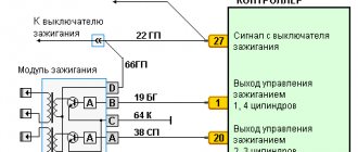
The schematic diagram of the VAZ 2106 ignition coil is located here. The figure shows how the ignition coil is connected in the standard version.
The ignition coil, the price of which is acceptable for most Russian motorists, has the nomenclature code 8352.12. and is an oil-filled tank with an open-type magnetic wire.
The standard ignition coil of the “six”, which is easy to buy at any specialized auto parts store, is equipped with 3 contact terminals: “B”, “K” and an output for the central high voltage wire. The ignition coil is connected in the following way: the positive wire of the battery is connected to terminal “B” through the ignition switch contact. Output “K” is connected to the output contacts of both windings of the ignition coils and the negative wire of the battery through the switch.
The high voltage output is connected to another contact of the secondary winding and a high voltage wire contact leading to the breaker distribution element, which, with the rotational movement of the slider, distributes the high voltage current to the spark plugs.
Spark plug
Spark plugs type NA-P/11-AU. The candle markings are deciphered as follows: N - non-separable; A - metric cutting 14 X 1.25 mm; 11—length of the screw-in part of the housing in mm; 11—length of the insulator skirt in mm; A—type of the upper nut of the central electrode; U is an insulator made from uralite mass.
A shaped nut is screwed onto the upper end of the central electrode, onto which the spring tip of the high voltage wire is placed. The tip ensures reliable contact and quick removal and installation of the wire on the spark plug.
The spark plug is sealed in the threaded hole of the cylinder head with a copper-asbestos gasket placed under the support end of the spark plug housing,
The normal gap between the spark plug electrodes should be within 0.6-0.7 mm.
How to install a distributor and configure it on a VAZ 2101 solved 1 answer
The first step is to remove the terminal from the battery, then disconnect the wires from the ignition coil, disconnect the central high-voltage wire, and remove the distributor cover. Next, you need to set the position of the slider so that it is rotated at an angle of 90° with respect to the engine. With this approach, replacing the distributor will have virtually no effect on the ignition timing. You unscrew the spark plug of the first cylinder, plug the spark plug hole with a rag, and begin to manually turn the crankshaft pulley clockwise, if you look at the engine against the movement of the car, until the rag jumps out of the spark plug hole. It is best to turn the engine with a ratchet wrench specially purchased for this purpose (or made independently according to a sample). In order for the position of the new distributor to be the same as the old one, you need to make a mark on the cylinder block as shown in the figure.
Adjustment with strobe light
We hook the strobe light to the car's network. You need to remove and plug the vacuum corrector hose from the distributor. Now the engine needs to be started and warmed up to a temperature at which it will stable idle speed. Then you need to loosen the bolt that secures the distributor body. The strobe light must be directed at the pulley, which is located on the crankshaft.
Now we begin to turn the distributor until the mark on the pulley aligns with the marks on the timing cover . In this position, the distributor body is fixed.
Electronic ignition system design
1) Sensor-distributor, acting as a contactless distributor. 2) Switch, the functional purpose of which is to interrupt the current of the primary circuit of the ignition coil in accordance with the signals of the sensor-distributor. The circuitry of this device provides a mode for automatically shutting off the current passing through the ignition coil when the power plant is not working (the ignition is on). 3) An ignition coil that converts an intermittent low voltage current (12 Volts) into a high voltage current (10-20 Kilovolts), initiating a “breakdown” » air gap on the spark plug electrodes. 4) A set of wires. 5) A set of spark plugs that ignite the fuel-air mixture through a spark discharge. The use of spark plugs in BSZ that are not designed for a high-power spark discharge is not recommended, since they quickly fail due to overheating.
Non-contact ignition system device
The schematic diagram of the VAZ contactless ignition of the sixth model is located below.
1. Contactless ignition distributor sensor. 2. Candles. 3. Shielded protection. 4. Non-contact type sensor. 5. Bobbina. 6. Generator element. 7. Ignition switch component. 8. Battery. 9. TC – transistor equipment with a switching circuit (transistor switch).
In such a complex, a non-contact ignition distributor is used to disconnect the low-voltage circuit, which works to open and close the electrical circuit, “locking” or “opening” the output transistor. This system allows you to increase the voltage on the electrodes of the spark plugs and, thereby, increase the energy of the spark discharge. At the same time, the voltage indicator on the spark plug elements does not decrease at low values of rotation of the crankshaft of the power plant, which makes the starting value of the motor much better.
Such non-contact ignition, the price of which is quite high, has significant advantages over the contact system.
Main elements of the ignition system
Now we need to consider the common elements of all ignition systems. They are the same in all, regardless of whether the VAZ-2106 has an electronic ignition system or a contact one. Firstly, candles are everywhere. They consist of a central electrode, with a small gap between it and the ground. It is isolated from the body by a ceramic element. Rare candles live 30 thousand km. mileage, and some even collapse. They burn out so that part of the central electrode falls into the cylinder. For this reason, it is necessary to replace them in a timely manner.
Secondly, armored wires connecting high-voltage parts. They consist of a special fiber through which a high voltage pulse is transmitted. There are five wires in total - four for connecting the distributor cap to the spark plugs. And one is for connecting the coil to the distributor. Thirdly, it is present in all designs, although they have slight differences. Fourthly, the ignition coil is a transformer capable of tens of times increasing the voltage supplied to the primary winding. But the electronic ignition circuit of the VAZ-2106 turns out to be a little more complicated than that used in the classical system.
Main elements of the ignition system
These include:
- Breaker-distributor. Initially, the first models until the 80s of the twentieth century were equipped with the R-125B device. It was equipped with a mechanical octane corrector, which adjusted the angular value of the ignition timing in a small range, but it was not equipped with a vacuum type regulator. After this, the ignition and fuel supply systems were modernized, as a result of which a distributor with a regulator of the vacuum operating principle and a compatible “Ozone” carburetor appeared.
- Bobbin B117-A is a contour type, with a disconnecting magnetic circuit, filled with special oil, sealed.
- Spark plugs A17DV or their export analogues.
- Ignition switch VK347 with an anti-theft gadget, operating on the following principle: after the ignition key is moved to position III “Parking”, a metal lock pops out of the body part, which falls into a special groove in the steering shaft and does not allow it to rotate.
For emergency repairs of the ignition system of a VAZ 2106 car, it is necessary to have in stock the parts that most often fail. This is a reel and a distributor capacitor; they do not take up much space. Unfortunately, they cannot be repaired.
Device malfunctions
Replacement and repair of the distributor on the domestic “six” is carried out in the event of incorrect operation of the mechanism.
We recommend: Daewoo Matiz - fuses and relays
Below are the main symptoms of breakdowns that indicate possible malfunctions:
- The vehicle jerks while driving. Moreover, these jerks are completely uncharacteristic of a car.
- The engine generally does not start.
- When trying to accelerate the car, the car may also jerk, and the acceleration process itself takes a lot of time, and the engine may detonate - the piston rings knock.
- Increased fuel consumption.
As you can see, in general the symptoms are similar to those that appear when the ignition is set incorrectly. Of course, if such symptoms appear, it cannot be said for sure that the fault lies in the distributor, but attention should also be paid to diagnosing this unit.
As for the breakdowns that may force the car owner to repair or replace the mechanism, they are as follows:
- The unit slider is worn out and burnt out.
- The problem lies in the cover itself - the contacts on it could have burned out.
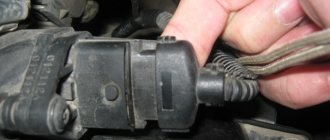
- Hall sensor failure. The problem may be associated not only with a breakdown of the controller, but also with poor contact on the regulator plug.
- Another reason that domestic drivers encounter quite often is the distributor bearing. After a long period of use, it could become loose, but it could also simply jam.
- Presence of mechanical damage, including cracks on the cover.
- Engine fluid gets into the distribution unit; usually the problem is related to the seal of the cap.
Adjustment how to set
It is recommended to use a special tool - a strobe light - to adjust contactless ignition. But if it is not there, you can use the following method.
- We set the distributor slider: unscrew the first spark plug, plug the hole with a finger and turn the crankshaft pulley. If air begins to press on your finger, it means you are on the compression stroke. At this moment, position the distributor so that the slider faces the first cylinder.
- Seize the moment of ignition. To do this, connect the central wire from the coil to the spark plug and short it to ground. Turn the distributor against the movement of the slider until the spark jumps from the spark plug. This point should be in the area where the slider interacts with the first cylinder.
- Set the ignition timing completely: with a warm car in second gear, give the gas sharply to the floor. When detonation is heard, set it later, if not, then set it earlier.
Setup video
Contactless ignition uses two important devices - a switch and a Hall sensor. The distributor and sensor must be compatible with each other. The new ignition coil must be an oil-filled type. It is better to take the wires for connecting the system from Niva.
In my free time, I read a lot, play airsoft (a team military sports game) and amateur radio communications. Lots of professional connections. My strengths: communication skills, endurance, responsibility.
What is called ignition timing: main points
The fuel mixture in the cylinder ignites quickly, but not instantly - a certain amount of time passes (about a second) from the moment the spark is formed and the gases expand until the system is activated. During this time, the piston has time to fire, travel the necessary distance and take part in the ignition process. In order to understand what is called the ignition timing angle, it is necessary to understand how the car ignition system as a whole works.
The moment of ignition occurs at the moment when the piston is on the compression stroke and gradually, smoothly approaches TDC. Then the combustion process occurs of a mixture formed from air (not pure oxygen) and gasoline (or diesel fuel, depending on the type of engine used), which form gases characteristic of the reactions taking place. They actively and without stopping push the piston entering the assembly in a downward direction - this moment is called the power stroke.
The energy generated (released) at the moment of direct combustion transforms into another form - mechanical energy that directly starts the crankshaft. The moment of ignition in 95% of cases is determined by its position relative to TDC. In various diagrams or graphs that discuss this process, it is customary to denote the angle in degrees.
Important to remember! If the angle deviates slightly from the normal value towards an increase, then the moment when ignition occurs is called early. Downward changes guarantee later ignition. In these cases, it is necessary to adjust the ignition timing.
All work is divided into several actions that must be performed sequentially. Their order is as follows:
- The engine will need to be turned off (it must cool down if the problem occurs on the road);
- Control is carried out to ensure that the car does not stand in gear (a standing brake is used for this);
- The car key is removed from the ignition;
- You will need to search for marks that should be located next to the timing belt gear;
- The same mark is revealed on another part - the flywheel;
- Then the adjustment of the ignition timing continues - it is necessary to disconnect the wire (it is high-voltage, you should remember this) that approaches the spark plug from the cylinder closest in distance to the radiators (the first one);
- You will need to insert a new spark plug into the wire;
- For convenience, it should be attached to a ground, which may be a hose holder that supplies fuel, located on the valve cover;
- Next you will need to remove the cover from the toggle switch;
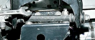
- The crankshaft key is placed on the nut located on the flywheel (the operation is performed on the left side of the car);
- The crankshaft will then need to be turned towards you! (if you twist away from you, the flywheel will unscrew);
- While rotating the flywheel, it is necessary to observe the distributor slider, adjusting its position if necessary so that it is in the contact area of the first cylinder.
How to set the ignition timing You should also take into account the values for the marks:
- long – 00;
- average length – 50;
- short – 100.
They vary and depend on the type of engine and make of the car.
After the marks have been set and all the necessary measurements have been made, the key should be removed from the flywheel. The toggle switch cover needs to be returned to its place. At the next stage of work, the car’s ignition can be turned on.
The motor must remain off (not running). Next steps:
- The nut securing the toggle switch is released (it, in turn, turns counterclockwise);
- Then the toggle switch turns, but in a clockwise direction (you will need to perform the action until a spark jumps) It is recommended to repeat the action 2-3 times;
- The toggle switch is fixed in the position where the spark appears;
- The wire (high voltage) is returned and attached to the spark plug of the first cylinder.
The final step is to check the ignition timing setting visually and then during actual movement (driving a car).
Attention! Before the first movement after adjustment, it is necessary to warm up the engine to the recommended (operating) temperature.
How to disassemble the mechanism at home, see the video below (the author of the video is Roman Romanov).
Signs of incorrect ignition timing setting
These include:
- the vehicle does not reach the maximum speed of the power plant;
- increased fuel consumption;
- the engine idles unevenly;
- the engine unit overheats;
- After the engine stops running, detonation occurs.
Correct installation of the VAZ 2106 engine ignition system consists of 3 stages:
The first stage is a change in the angle of contacts that are in a closed form. The second stage is setting the ignition timing of the VAZ 2106, and the third is adjusting the ignition system while the vehicle is moving. This ignition setting is carried out when the “six” is equipped with a contact ignition system or a transistor switch is installed.
- Unfasten the latches of the breaker-distributor cover. With a contact system, we first clean its contact group with a needle file and test the degree of their interaction. If necessary, slightly tighten the fixed-type contact.
- Using a special key for rotating the crankshaft, we select a position of the product when the contact gap becomes extremely large (if it is absent, we put the manual transmission in the 4th gear position and select this moment by moving the vehicle).
- We unscrew the fasteners that secure the group of contacts on the bearing base.
- Using a special set of probes, we select a product with a 0.4 mm template and adjust the gap between the contacts so that the template hardly passes between the contacts.
- Screw in the fasteners and fix the position of the contacts.
- We carry out verification measurements with 0.35 mm and 0.45 mm probes. In the first case, free movement in the gap of the contact group is allowed, and in the case of the second probe, the passage of the template is not allowed.
The principle of operation of the contact group
ATTENTION! A completely simple way to reduce fuel consumption has been found! Don't believe me? An auto mechanic with 15 years of experience also didn’t believe it until he tried it. And now he saves 35,000 rubles a year on gasoline! Read more"
The CG or contact group functions in a special way. It is constantly under tension, which in most cases explains the burning. To minimize burning, and therefore additional current, a capacitor is connected. The latter is located at the bottom of the classic layout distributor.
In the process of opening the CG, a spark appears in the gap, sometimes too powerful. This spark charges the capacitor. However, a powerful spark appears only at the moment the CG opens, but the spark is minimized, its strength is reduced to nothing as the gap opens completely or increases. And at this very time, the process of discharging the capacitor, storage tank or heat exchanger (as it is also called) begins. At this time, voltage goes directly to the coil, or rather, to its main winding.
If you try to deepen your knowledge, you can also pay attention to the fact that in the process a current pulse is created, allowing the magnetic flux to disappear. But the most important thing is not this, but the fact that with the help of a pulse it is possible to achieve a current with a higher voltage on an additional winding.
Capacitor capacity may vary. It depends on the specific make or model of car. For example, in domestic VAZ models the capacitance of the part is 0.2-0.25 microfarads.
When the value increases or decreases, this necessarily leads to a decrease in the current on the additional winding.
Electrical discharges that occur when the breaker contacts open cause erosion and corrosion. Erosion is accompanied by the transfer of metal from one contact to another, as a result of which a tubercle is formed on the moving contact, and a depression (crater) is formed on the fixed contact. Corrosion of the breaker contacts is accompanied by the formation of non-conducting films on them. Both factors lead to disruption of the regularity of the neoplasm, and therefore to missed flashes in individual engine cylinders. To ensure reliable operation of the breaker contacts, the service book provides for cleaning the contacts every 10,000 km and then adjusting the gap between them.
Lubrication work for the breaker-distributor units at intervals (every 10,000 km) coincides with cleaning and adjusting the breaker contacts. Therefore, it is most advisable to combine these works and perform them simultaneously.
Cleaning and adjusting the breaker contacts should be done in the following sequence.
1. Level the contact surfaces using a thin velvet file. At the same time, remove the bump on the moving contact and slightly smooth the surface of the other one, on which a depression (crater) has formed.
2. After cleaning, wipe the contacts with a lint-free cloth moistened with pure gasoline, and by pulling the moving contact for a few seconds, allow the gasoline to evaporate from the surface of the breaker contacts.
To ensure normal operation of the ignition system, the gap between the breaker contacts must be adjusted within 0.35-0.45 mm.
Adjust the gap in the following sequence.
1. Release the latches, remove the distributor cover without removing the high voltage wires from it, and remove the rotor.
2. Slowly turning the engine crankshaft with the starting handle, set the cam to the position where the gap between the contacts of the breaker is greatest, that is, when the pad of the lever 15 (Fig. 9) of the breaker is installed on the top of the edge of the cam.
3. Check the gap between the contacts with a flat feeler gauge (included in the tool kit supplied with the car). If the gap does not correspond to the value indicated above, loosen the locking screw 10 using a screwdriver and, turning the head / adjusting eccentric with a screwdriver, set the required gap. 4. Tighten locking screw 10 with a screwdriver. 5. Using a feeler gauge, make sure that the gap between the breaker contacts is adjusted correctly. If the gap is not adjusted correctly, perform steps 3, 4, 5 again.
6. Place the rotor and distributor cap and secure it with the latches. It should be noted that after adjusting the gap between the breaker contacts, the correct setting of the ignition timing is disrupted. Therefore, the ignition installation must be checked and, if necessary, adjusted.
To lubricate the breaker-distributor you must:
1. Turn the cap 11 of the oiler cap one turn to supply lubricant to the distributor shaft. 2. Place one drop of engine oil on the axis 16 of the breaker lever 15. 3. Place 4-5 drops of engine oil into the cam bushing, having first removed the rotor and the felt pad 13 underneath it. 4. Felt brush 2 for lubricating the breaker cam should not be lubricated during the first 30,000 km of the vehicle. After this run, the brush must be removed from the holder, cut off the hard crust that has formed on its edge, place the brush in the holder and add 2-3 drops of oil. Subsequently, every 10,000 km of the vehicle, it is necessary to lubricate the brush with one drop of engine oil. Please note that the distributor-breaker should be lubricated only in accordance with the above recommendations. The principle of not spoiling porridge with oil does not apply here. With excess lubrication, the contacts of the breaker become oily, which leads to their accelerated burning, interruptions in engine operation, difficult starting, etc.
( 1 rating, average 5 out of 5 )
Checking the coil
In the process of checking the performance of the coil, the first thing to do is check the voltage supply to it.
For this purpose, the voltage supply is turned on and then it is measured between terminal B+ and ground. This value is 12 V. If voltage is not supplied to the coil, then the reason for its absence should be sought in the lock. If normal voltage is present and there is no spark on the spark plugs, it is necessary to measure the resistance of the windings. To do this, the contacts of the measuring device are applied to two side terminals. For the primary winding, the resistance value should be 3-4 ohms.
The resistance of the secondary winding is within 7-9 Ohms. The coil cannot be checked for the presence of a spark by leaning the high-voltage wire against the motor body, since in this case the gap becomes so large that the increased resistance causes breakdown of the winding of the unit, and this leads to failure.
Checking the adjustment results
Let's move on to the last stage, we need to check the results obtained. The results are checked based on the car's behavior on the road. You need to warm up the engine, drive out onto a flat section of the road, pick up a speed of 40-50 km/h, engage fourth gear and sharply press the gas pedal . Within 1-2 seconds, characteristic knocking sounds similar to clattering will be heard, and the car will immediately begin to confidently pick up speed.
If no sounds are heard, then you need to turn the distributor counterclockwise one notch, this procedure must be repeated until a sound is heard.
The cause of the malfunction may also be a deviation of the fuel composition from the nominal one, as well as incorrect operation of the distributor systems.
“>
Malfunctions of the six ignition system
When operating a vehicle, the following malfunctions of the ignition system occur, which must be eliminated before further driving the vehicle.
| Malfunction | Remedy |
| The contact group has a coating of dirt, is oxidized or there are contact burn points, the distance between the contacts is increased | It is necessary to clean the contact group and adjust the gap |
| Weak fasteners or wiring caps in the low-voltage circuit have oxidized, a broken wire or a short circuit to the car body | Test the wiring and their connections, replace damaged sections of the circuit |
| Defective ignition switch (no contact closure) | Test the area, replace the defective contact element of the ignition switch |
| The capacitor is broken and does not hold capacity | Replace the product |
| There is no voltage in the primary type bobbin winding | Replace the product |
| Incorrect adjustment size in the distributor contact group | Set recommended size in contact group |
| Excessive wear of the PCB pad or increased diameter of the distributor lever bushing | Replace contact group |
| Defect in the bearing of the movable type distributor plate | Replace the bearing or the entire distributor |
| The ignition spark plug elements have an uncertain contact in the threaded part of the cylinder head, the spark plug caps from the insulated HV wires have broken or become oxidized; the insulated HV wires are dirty or their insulating layer is damaged | Test the contacts and, if necessary, restore the joints, clean or change the wiring |
| The corner of the distributor cover has undergone severe wear or has become defective and is in a non-contact state | Check the carbon of the distributor cap and, if necessary, replace it |
| Loss or loss of voltage through chips, through cracks or burnout points in the cover or rotor part of the distributor, as well as through a layer of soot or drops of moisture on the internal cavity of the distributor cover | Carry out a check, clean the cover from foreign layers of moisture and soot, replace the distributor elements (cover and rotor) if they are damaged |
| Failure of the resistance in the slider (distributor rotor) | Replace the slider resistance |
| The car bobbin has external or internal defects | Replace the car bobbin |
| The glow elements of the spark plugs (electrodes) are dirty with oil or the gap between the interacting elements is set incorrectly | Clean the spark plug elements and carry out adjustments to align the gap between the interacting elements |
| Ignition spark plug elements have external defects in the form of cracks and chips on the insulator element | It is necessary to replace spark plug elements with updated products |
| Incorrect connection of high-voltage wires to the contacts on the car distributor cover | Connect the high voltage wires according to the appropriate diagram (1-3-4-2) |
| Incorrect installation of the ignition in the vehicle | Test the installation of the MH and, if necessary, adjust it |
The table below will help you diagnose and troubleshoot problems that may arise.
Spark for everyone and equally
The distribution of high voltage electrical energy between all engine cylinders is ensured by a rotor (runner) mounted on the distributor shaft, as well as a distributor cap, which has a contact group and sockets for high-voltage wires. Electricity enters the slider through a spring-loaded carbon contact, goes along its bus to the side contact and then to the individual high-voltage wires of the cylinders. In a mechanical sense, there is no contact between the slider and the sockets of the spark plug wires: the transmission of electricity with a voltage of 15 - 25 thousand volts occurs through an air gap of 0.4-0.8 mm.
However, the simple design of the “distribution” part of the distributor does not guarantee its failure-free operation. Invisible cracks and contamination of the cover can cause power loss to ground, which manifests itself in unstable operation of the motor and problems with starting, especially in wet weather. The likelihood of such breakdowns is reduced if these parts are kept clean.
Sometimes the noise suppression resistor, which is found in some distributors, also burns out. Instead of a faulty resistor, you can temporarily install a “bug” jumper.
Distributor parts cannot be repaired. It is possible to restore only the contact of the runner, the edge of which, as a result of long-term use, is “eaten up” by erosion. A strip of brass is soldered to the worn area. The spring-loaded central carbon electrode can be temporarily replaced with the stem from a large cylindrical battery.