Car designs are rich in electrical equipment and electronics. Electrical wiring for a car is as important as veins are for the human body. Experienced drivers can navigate this web of wires without any problems, but for inexperienced drivers, learning to read electrical diagrams is useful, because if a problem occurs, you can figure out where it happened and what to check before calling a car service center.
There are three main lines in the wiring of the Lada Priora electrical circuit: for supplying energy, the starting circuit and the circuit for supplying energy consumers. Each of the car's systems is connected by a bundle of wires that connect instruments and electrical equipment. There are four main harnesses in the Priora electrical circuit:
- coming from the instrument panel;
- providing motor control;
- front electrical harness;
- rear electrical harness.
All these harnesses are connected to each other using detachable connections. The connectors are located under the dashboard. Each of the harnesses is assigned a serial number.
In addition to the main ones, there are secondary electrical harnesses:
- installed in the front passenger door;
- identical in both the left and right rear doors;
- installed in the driver's door;
- connecting the backlight of the license plate;
- connecting the electrical package.
Each element in the diagram corresponds to a number with an explanation. Since all elements are standardized, their designations are identical on car diagrams of all car manufacturers. Next to each electrical appliance, the connectors that go to them are indicated. The pins or sockets of the pads are also numbered. Each block has colored wires (the color of the wires in the diagram corresponds to the color of the wire in the car).
At the top, the wires are numbered with numbers written through a fraction. The first number indicates which electrical appliance it goes to. The second number indicates which connector the wire goes to. Wires in electrical wiring connected using connectors (marked with the letter C and a number), or using terminal blocks (marked with the letter S and a number).
The layout of pins, or connecting contacts to certain nodes is called pinout.
Electrical connection diagram for the ignition system of a Lada-Priora car
The spark ignition system wiring diagram section contains graphical information about the supply of current to the main automated instruments and the vehicle's electronic engine control system. From them, the voltage is distributed to the main blocks, power plants, as well as control sensors and ECUs.
| Contact no. | Decoding |
| 1 | ECU power supply |
| 2 | Connecting the ignition system harness to the dashboard harness |
| 3 | Fuse box |
| 4 | Measuring device for determining the speed of movement |
| 5 | Road roughness detection sensor (located on the shock absorber support cup) |
| 6 | Oil pressure warning light indicator |
| 7 | TPS sensor |
| 8 | DTOZh sensor |
| 9 | Coolant temperature indicator |
| 10 | MAF sensor (MAF sensor) |
| 11 | Idle air valve (IAC) |
| 12 | Main fuel pump relay |
| 13 | Power fuse for the fuel pump |
| 14 | Starter relay |
| 15 | Starter relay fuse (15A) |
| 16 | ECU fusible link |
| 17 | Crankshaft position sensor (CPS) |
| 18 | Oxygen sensor |
| 19 | Camshaft phase sensor |
| 20 | Knock Level Sensor |
| 21 | Solenoid valve for filter purge and vapor recovery |
| 22 | Lambda probe |
| 23 | Electronic ignition module power supply |
| 24 | Supplying voltage to spark plugs |
| 25 | Fuel injector power |
| 26 | Harness block from ignition coil to ECM harness |
| 27 | Harness block from the ignition system to the ignition coil wiring harness |
| 28 | Engine computer connector to injection system |
| 29 | Injection system harness block to ignition system harness |
| A | To terminal (+) AB |
| B1, B2 | Places for attaching ground wires of the ignition system |
| C1 | Place of attachment of the ground wire coming from the ignition coils |
Ignition system electrical harness, 2170-3724026.
Ignition coil electrical harness, 1118-3724148.
Injector electrical harness, 11186-3724036.
Car diagram - Lada Priora
Electrical equipment diagram for a car such as VAZ-2170 Lada Priora 2004+. The Lada Priora is equipped with an injection 16-valve engine mod. located across the engine compartment. VAZ-21126-00 with a working volume of 1.6 liters. The engine is equipped with a distributed fuel injection system and an exhaust gas catalytic converter, structurally made in a single block with the exhaust manifold (catcollector). The body is load-bearing, all-metal, of welded construction, with hinged doors, front fenders, hood and trunk lid.
Instrument panel harness connection diagram
1, 2, 3 — instrument panel harness pads to the front harness; 4 — instrument panel harness block to the rear harness; 5 — contacts of the mounting block; 6 — brake light switch; 7 — instrument cluster; 8 — lighting control module; 9 — driver airbag module; 10 — sound signal switch; 11 — diagnostic block; 12 — on-board computer mode switch; 13 — ignition switch (lock); 14, 15 — blocks to the electric booster control unit; 16 — electrical package controller; 17 — light signaling switch; 18 — windshield wiper and washer switch; 19 — gearmotor for air flow distribution; 20 — heater control unit; 21 — heater motor switch; 22 — rear window heating switch; 23 — hours; 24, 25 — blocks of the instrument panel harness to the radio equipment; 26 — alarm switch; 27 — glove box lighting; 28 — glove compartment lighting switch; 29 — block of the instrument panel harness to the harness of the electronic engine management system; 30 — airbag system control unit; A1, A2, A3 — grounding points of the instrument panel harness; B - mounting block block
Wiring diagram for connecting the front wiring harness of a car
1 - starter; 2 - battery; 3 - generator; 4 — blocks of the battery harness, starter and front harness; 5, 6, 7 — front harness pads to the instrument panel harness; 8 — engine compartment lamp switch; 9 — left headlight; 10 — right headlight; 11 — brake fluid level sensor; 12 — air temperature sensor; 13 — electric motor for washers; 14 — reverse lamp switch; 15 — engine electric fan; 16 — heater damper gearmotor; 17 — additional resistor; 18 — windshield wiper motor; 19 — main fuse block; 20 — heater electric motor; 21 - alarm signal; 22 — sound signal; A1, A2, B1, B2 - grounding points of the front harness
Wiring diagram for connecting the harness of the electronic engine management system on Lada Priora
1 - ECU; 2 — ECM harness block to the instrument panel harness; 3 - main fuse block; 4 — speed sensor; 5 — rough road sensor; 6 — warning lamp sensor for emergency drop in oil pressure; 7 — throttle position sensor; 8 — coolant temperature sensor; 9 — coolant temperature indicator sensor; 10 — mass air flow sensor; 11 — idle speed regulator; 12 — electric fuel pump relay; 13 — fuse for the electric fuel pump power supply circuit (15 A); 14 — ignition relay; 15 — ignition relay fuse (15 A); 16 — ECU power supply fuse (7.5 A); 17 — crankshaft position sensor; 18 — control oxygen concentration sensor; 19 — phase sensor; 20 — knock sensor; 21 — solenoid valve for purge of the adsorber; 22 — diagnostic oxygen concentration sensor; 23 — ignition coils; 24 — spark plugs; 25 — nozzles; 26 — block of the ignition coil wiring harness to the ECM harness; 27 — ECM harness block to the ignition coil wiring harness; 28 — ECM harness block to the injector harness; 29 — injector harness block to the ECM harness; A - to the battery terminal; B1, B2 — grounding points of the ignition system harness; C1 - ignition coil wiring harness grounding point
Car rear wiring harness connection diagram
1 — block of the rear wiring harness to the instrument panel harness; 2 — block of the rear wiring harness to the left rear door harness; 3 — rear wiring harness block to the right front door harness; 4 — electrical package controller; 5 — left side direction indicator; 6 — right side direction indicator; 7 — interior lamp; 8 — parking brake warning lamp switch; 9 — left lamp; 10 — right lamp; 11 — cabin air temperature sensor; 12, 13, 14, 15 — interior lamp switches; 16 — block of the rear wiring harness to the left front door harness; 17 — rear wiring harness block to the right rear door harness; 18 — rear harness pads to the rear right loudspeaker; 19 — rear harness pads to the rear left loudspeaker; 20 — cigarette lighter; 21 — electric fuel pump module; 22 — trunk lighting switch; 23 — rear window heating element; 24 — trunk lighting; 25 — additional brake light; 26 — trunk lock drive switch; 27 — rear wiring harness block to the license plate light harness; 28 — rear wiring harness block to the right front door harness; A1, A2, A3, A4 — grounding points of the rear wiring harness; XP1, XP3 - electrical package controller connectors
Pinout for connecting the front wiring harness on a Lada Priora VAZ 2170
From the front electrical harness, current is supplied to those electrical devices that are located in the front engine compartment of the car, such as a complex of lighting equipment, a sound device, generator and starter connections, an electric washer motor, a cooling system fan, etc. The harness is connected by plug-sockets 18,19,20 to the bundle of wires of the panel instruments, and by plug 37 to the terminal block of the rear harness.
| Contact no. | Decoding |
| 1 | Commutator DC Motor |
| 2 | Battery |
| 3 | Power generator |
| 4 | Battery, starter and front harness connectors |
| 5-7 | Front harness connectors to instrument panel harness |
| 8 | Engine compartment light breaker |
| 9-10 | Headlight units |
| 11 | Brake fluid level indicator |
| 12 | Outside temperature sensor |
| 13 | Electric windshield washer motor |
| 14 | Reverse sensor |
| 15 | Radiator cooling fan |
| 16 | Heater damper motor |
| 17 | Backup load resistor |
| 18 | Front window wiper motor |
| 19 | Main relay and fuse box |
| 20 | Heater motor |
| 21,22 | Sound signaling devices |
| A1, A2, B1, B2 | Front harness grounding locations |
The front electrical harness corresponds to serial number 2170-3724010;
Battery wiring harness with housing number 2170-3724080;
The electrical harness going from the battery to the starter is designated with the number 2170-3724070.
Designations for the rear wiring harness of the VAZ Priora
The wiring harness, located in the passenger compartment and rear of the car, has the shape of a flexible barrel with branches on which contacts are installed with blocks for docking with consumer electrical appliances. The rear electrical circuit is also connected to lighting fixtures, locks, power windows, front and rear doors.
The pinout of tips and terminals looks like this:
| Contact no. | Decoding |
| 1 | Dashboard |
| 2 | Left rear door wiring harness block |
| 3 | Right front door wiring harness block |
| 4 | Used double-glazed windows and door locks |
| 5 | Left turn signal |
| 6 | Right turn signal |
| 7 | Interior lighting module |
| 8 | Handbrake warning lamp switch |
| 9 | Left side light |
| 10 | Right side lamp |
| 11 | Interior temperature sensor |
| 12 | Interior light switch in the left front door pillar |
| 13 | Interior light switch in the front right door pillar |
| 14 | Interior light switch in the right rear door pillar |
| 15 | Interior light switch in the left rear door pillar |
| 16 | Driver's door wiring harness |
| 17 | Right rear door wiring harness |
| 18 | Rear right speaker |
| 19 | Rear left speaker |
| 20 | Cigarette lighter |
| 21 | Fuel pump block |
| 22 | Trunk light switch |
| 23 | Rear window heating device |
| 24 | Trunk light |
| 25 | Additional brake light |
| 26 | Tailgate lock switch |
| 27 | License plate lamp harness |
| 28 | Right front door harness block |
| A 1-A4 | Grounding |
| XP, XP3 | Electrical package power controller connectors |
The rear wiring harness is marked 2170-3724210.
Lada Priora operation and repair
We remove the lock to replace it, as well as when repairing the door (straightening, painting).
Comment
The door lock consists of an internal and external part. If the outer part is faulty, it can be replaced without removing the door trim.
Removal
1. Remove the door trim and remove the plastic film.
2. Disconnect the wiring block of the lock gear motor from the wiring harness block
3. Remove the gear motor wires from the clamp.
4. Using a slotted screwdriver, disconnect the plastic ends of the switch rods (cylinders) of lock 1 and the outer handle of lock 2 from the lock levers.
5. Using a TORX T40 key, unscrew the two screws securing the lock.
6. Remove the outer part of the lock.
7. Using a Phillips screwdriver, unscrew the three screws securing the inner door opening handle.
8. Using a Phillips screwdriver, unscrew the screw securing the inside of the lock to the door panel.
9. Remove the inner part of the lock assembly with the locking button rod and the gear motor from the door.
10. To remove the lock latch, mark its position on the B-pillar (with a marker or felt-tip pen).
11. Using a TORX T40 wrench, unscrew pin 1 of the lock and two screws from the fastener.
12. Remove the lock.
Comment
Shims can be installed under the retainer. They should be put in place during assembly.
Installation
Install the door lock in the reverse order.
Recommendation
It is convenient to put the plastic rod ends on the ball pins of the lock levers using sliding pliers.
We install the lock retainer following the marks made. If the door does not close well (for example, with a metallic knock or you have to slam the door hard to close), adjust the lock (see below).
Adjustment
Comment
The door lock is adjusted by changing the position of the latch on the pillar. When closing the door, the protruding part of the latch body should not touch the door and the elements of the outer part of the lock. The latch pin must fit into the slot on the outer part of the lock without touching the edges of the slot.
1. Loosen the tightening of the latch pin and two screws securing the latch (see above). By changing the position of the latch in the vertical plane, we achieve the optimal position of the latch pin in the lock slot.
2. The tightness of the door cover is adjusted by moving the latch in the horizontal plane.
3. If the latch touches the lock or door, accordingly increase or decrease the number of shims installed under the latch.
Recommendation
You can make additional shims yourself by cutting them out of sheet metal (preferably aluminum alloy).
4. After completing the adjustment, tighten the fastening screws and the lock lock pin.
Rear license plate light pinout
According to traffic regulations, the state license plate illumination must always be in working order. For lighting, W5W incandescent lamps are connected, each with a power of 5 W.
The small wiring harness for the rear license plate light (harness serial number 2170-3724214) consists of wires with cream ends and is located in the luggage compartment. The operation of the entire lighting system depends on its quality. The harness responsible for the rear license plate illumination has 3 terminals:
| № | Decoding |
| 1 | Supplying voltage to the lights illuminating the rear number |
| 2,3 | License plate lamps |
| 4 | Electric tailgate lock motor |
Pinout for left front door
Most modern vehicles are equipped with a variety of driver comfort systems, one of which is the driver's door module.
The function of the button block located on the driver's door is to control the front windows and exterior mirrors, as well as the automatic locking of the car doors. The installed auxiliary left rear wiring harness (part number 21703-724551-90) comes complete with contact carriers made of electrically conductive materials.
| Contact no. | Decoding |
| 1 | Connector for the additional rear left harness to the rear harness |
| 2 | Rear left harness connector to front left speaker |
| 3 | Electric window lift |
| 4 | Armrest control module |
| 5 | Electric drive for locking the left front door |
| 6 | Left outer rear view mirror control chip |
Reasons for the breakdown of the ICC
As it would seem, the failure of the light control module on a Priora depends on the number of times the headlights are turned on and off, but this is not the case. Most breakdowns occur not due to the physical impact of a person on a given electrical appliance, but precisely due to the load from constantly switched on headlights. How is this explained?! Driving for a long time with the headlights on provokes heating of the tracks in the MUS board, thereby, when the electrical wiring heats up, its resistance increases and these tracks break.
Priora with daytime running lights
This problem occurs quite often and most prior managers run to the store and buy a new module at a very expensive price. Never rush into buying an ICC as it can be repaired without spending a penny.
If the light control module fails on the road, then you can read how to turn on the lights when the MUS is not working on a Priora here.
Front Passenger Door Wiring Harness
The electrical wiring of the left and right front doors of the car differs in the additional control buttons for mirrors and power windows on the driver's door.
The factory original front passenger door wiring harness, part number 21703-3724550 -90, duplicates the power supply from the passenger door center front keypad.
There are 7 connectors coming out of the harness.
| Contact no. | Decoding |
| 1 | Connector of the right rear additional harness to the rear harness |
| 2 | Rear left harness connector to front speaker |
| 3 | Window lift motor |
| 4 | Electric window lift switch |
| 5 | electric front passenger door lock |
| 6 | Motor controls the position of the outer right mirror and its heating |
| 7 | Connector of the right rear additional harness to the rear harness |
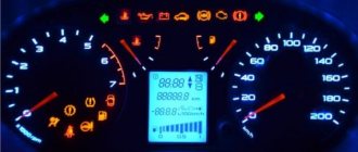
Electrical diagram of the Lada Priora dashboard
The dashboard displays driving characteristics, the current state of vehicle systems that ensure traffic safety, as well as the correct operation of the entire vehicle. The instrument panel wiring diagram helps to navigate the instrument and alarm indications in cases of malfunction. The instrument panel harness is marked with number 2170-3724030.
| № | Decoding |
| 1-3 | Front harness contact group |
| 4 | Rear harness contact group |
| 5 | Power supply from the central electrical system module |
| 6 | Connecting contact system for brake light group |
| 7 | Dashboard display |
| 8 | Lighting monitoring and control module |
| 9 | Contact group of the driver's emergency airbag activation module |
| 10 | Horn switch |
| 11 | Diagnostic connector |
| 12 | On-board computer control mode switch |
| 13 | Ignition coil controller |
| 14, 15 | Supply voltage to the electric power steering control unit |
| 16 | Electrical functionality controller |
| 17 | Light switch |
| 18 | Wiper switch |
| 19 | Air flow distribution gearmotor |
| 20 | Stove control unit |
| 21 | Heater drive switch |
| 22 | Heated rear window switch |
| 23 | Onboard clock |
| 24,25 | Instrument panel harness connector to radio |
| 26 | Emergency button |
| 27 | Glove box light |
| 28 | Glove box light control button |
| 29 | Ignition system harness |
| 30 | Control unit for airbag systems |
| A1, A2, A3 | Instrument panel harness grounding locations |
| B | Mounting block block. |
Lada Priora wiring block diagrams
1,2,3,4 – blocks of the instrument panel wiring harness to the blocks of the rear wiring harness; 5 — block of the instrument panel wiring harness to the block of the ignition system wiring harness; 6,7,8 — blocks of the instrument panel wiring harness to the blocks of the front wiring harness; 9 – lighting control module; 10 – ignition switch; 11 – on-board computer mode switch; 12 – windshield wiper switch; 13 – passenger airbag module; 14 – light signaling switch; 15 – instrument cluster; 16 – hours; 17 – diagnostic block; 18 – recirculation switch; 19 – control unit for windshield wiper and external lighting; 20 – micromotor gearbox for driving the heater control damper; 21 – rear window heating switch; 22 – alarm switch; 23 – brake signal switch; 24 – electric amplifier control unit; 25,26 — blocks of the instrument panel wiring harness to the radio; 27 – mounting block: K1 – relay for turning on low beam headlights and side lights; K2 – relay for turning on the heated rear window; K3 - starter activation relay; K4 – additional relay; K6 – relay for turning on high speed windshield wiper (automatic mode); K7 – headlight high beam relay; K8 – sound signal relay; K9 – relay for turning on the alarm sound signal; K10 – relay for turning on fog lights; K11 – relay for turning on the electric heating of the front seats; K12 – windshield wiper activation relay (intermittent and automatic modes). 28 – lampshade lighting of the glove box; 29 – glove box lighting switch; 30 — automatic lighting control switch; 31 – electrical package controller; 32 – controller of the automatic climate control system; 33 – rotating device; 34 – driver airbag module; 35 – sound signal switch.
1 – oil pressure warning lamp sensor; 2 – coolant temperature indicator sensor; 3 — main fuse block; 4 – controller power supply fuse (7.5 A); 5 – fuse for the power supply circuit of the electric fuel pump (15 A); 6 – ignition relay fuse (15 A); 7 – Priora ignition relay; 8 – electric fuel pump relay; 9 – throttle position sensor; 10 — idle speed regulator; 11 — coolant temperature sensor; 12 – ignition system harness block to the instrument panel harness block; 13 — solenoid valve for purge of the adsorber; 14 – speed sensor; 15 — mass air flow sensor; 16 – crankshaft position sensor; 17 – diagnostic oxygen sensor; 18 – Priora Lada controller; 19 — rough road sensor; 20 – control oxygen sensor; 21 – pads for the ignition coil harness and ignition system harness; 22 – ignition coils; 23 – spark plugs; 24 – Lada Priora injectors; 25 - phase sensor; 26 – knock sensor; 27 – pads of the ignition system harness and injector harness.
1 – right headlight; 2 – right front speed sensor; 3 – reverse light switch; 4 – electric motor for washers; 5 – windshield wiper motor; 6 – engine compartment lamp switch; 7 – electric fan of the engine cooling system (left); 8 – starter 2170; 10 — rechargeable battery; 11 – main fuse block; 12 – VAZ2170 generator; 13 — ABS hydraulic unit; 14 – air temperature sensor; 15 – brake fluid level sensor; 16 – alarm signal; 17 – sound signal; 18 – left front speed sensor; 19,20,21 – front wiring harness blocks to the instrument panel wiring harness blocks; 22 – left headlight VAZ-2170; 23 – right fog lamp; 24 – left fog lamp; 25 – air conditioning system pressure sensor; 26 – air conditioning compressor; 27 – air conditioner electric fan (right); 28 – air temperature sensor (air conditioning system); 29 – rear window washer electric motor; 30 – block of the front wiring harness to the block of the heater wiring harness; 31 – right electric fan relay; 32 – left electric fan relay; 33 – additional relay (sequential activation of left and right electric fans); 34 – heater electric fan relay; 35 – compressor relay; 36 — compressor power supply fuse (15 A); 37 – fuse for the power supply circuit of the electric heater fan (40 A); 38 — front wiring harness block to rear wiring harness block; 39 – fuse for the power supply circuit of the right electric fan (30 A); 40 – fuse for the power supply circuit of the left electric fan (30 A).
1 – rear wiring harness block to the instrument panel wiring harness block; 2 – rear wiring harness block to additional wiring harness block 2 (left rear door); 3 – rear wiring harness block to side door wiring harness block (right front door); 4 – left side direction indicator; 5 – electrical package controller; 6 – right side direction indicator; 7 – interior lighting unit; 8 – handbrake warning lamp switch; 9 – left lamp of Lada Priora; 10 – right lamp; 11 – interior air temperature sensor; 12 – interior lamp switch in the driver’s door pillar; 13 – switch for the interior lighting in the pillar of the right front door; 14 – switch for the interior lighting in the pillar of the right rear door; 15 – interior light switch in the left rear door pillar; 16 – block of the rear wiring harness to the block of the wiring harness of the side doors 2 (left front door); 17 – rear wiring harness block to the additional wiring harness block (right rear door); 18 – blocks of the rear wiring harness to the rear right loudspeaker; 19 – blocks of the rear wiring harness to the rear left loudspeaker; 20 – cigarette lighter VAZ-2170; 21 – electric fuel pump module; 22, 23 – rear wiring harness blocks to instrument panel wiring harness blocks 2,3; 24 – trunk lighting; 25 – additional brake signal; 26 – trunk lock drive switch; 27 – interior lamp; 28 – rear wiring harness block to the front wiring harness block; 29 – left rear speed sensor; 30 – right rear speed sensor; 31 – sensor for automatic glass cleaning system (rain sensor); 32 – rain sensor sensitivity regulator; 33 – rear wiring harness block to instrument panel wiring harness block 4; 34 – block of the rear wiring harness to the block of the wiring harness of the parking system sensors; 35 – alarm unit for safe parking system; 36 – driver’s seat belt pretensioner; 37 – passenger seat belt pretensioner; 38 – rear wiring harness block to side door wiring harness block 3 (right front door); 39 – airbag control unit; 40 – parking system control unit; 41 – block of the rear wiring harness to the block of the rear additional wiring harness (tailgate); 42 – rear wiring harness block to rear additional wiring harness block 2 (tailgate); 43 – left seat heater; 44 – switch for electric seat heaters; 45 – right seat heater. 46 – rear wiring harness block to the parking system switch.
Useful: Lada Largus diagram
Pinout of the Lada Priora instrument panel connector
The information panel installed on the dashboard contains the most data.
Each auxiliary device is connected to the control lamps on the panel. A computer chip monitors the operation of all devices. Its mission is to control the operation of the panel in accordance with its firmware. All elements of this device are mounted on an electronic board, on which connecting tracks are applied: a microcircuit with an ECU, an LCD monitor, resistances, transistors, a connector socket for the wiring harness. There are 32 cells in the connector for connecting the instrument panel.
| № | Decoding |
| 1 | Electric power steering |
| 2 | Emergency control |
| 3 | Connection to oil pressure sensor |
| 4 | Parking brake indicator light |
| 5 | Electronic anti-theft device |
| 6 | Airbag control module |
| 7 | External lighting switch |
| 8 | Right turn signal indicator and doubler |
| 9 | Left turn signal indicator and backup |
| 10 | Engine control unit |
| 11 | Disabling the passenger's front airbag |
| 12 | Seat belt warning light |
| 13 | ABS brake system unit |
| 14 | Steering column switch button |
| 15 | Brake expansion tank indicator |
| 16 | ABS safety control module |
| 17 | Main beam headlight control unit |
| 18 | Shield backlight module |
| 19 | General disadvantage of the device |
| 20 | Constant positive battery terminals |
| 21 | Ignition switch contact |
| 22 | Fuel flow meter |
| 23, 24 | Steering wheel turn switches |
| 25,26 | Overboard temperature sensors |
| 27 | Fuel sensor |
| 28 | Speed sensor |
| 29 | Coolant temperature sensor |
| 30 | Tachometer signal |
| 31 | Shield diagnostics |
| 32 | Generator Regulator Relay Terminal |
Instrument cluster block diagram
| № | Decoding |
| 1 | Electric power steering |
| 2 | Emergency gang control VAZ-2170 |
| 3 | Connection to oil pressure sensor |
| 4 | Parking brake indicator light |
| 5 | Electronic anti-theft device |
| 6 | Airbag control module |
| 7 | External lighting switch |
| 8 | Right turn signal indicator and doubler |
| 9 | Left turn signal indicator and backup |
| 10 | Engine control unit |
| 11 | Disabling the passenger's front airbag |
| 12 | Seat belt warning light |
| 13 | ABS brake system unit |
| 14 | Steering column switch button |
| 15 | Brake expansion tank indicator |
| 16 | ABS safety control module |
| 17 | Main beam headlight control unit |
| 18 | Shield backlight module |
| 19 | General disadvantage of the device |
| 20 | Constant positive battery terminals |
| 21 | Ignition switch contact |
| 22 | Fuel flow meter |
| 23, 24 | Steering wheel turn switches |
| 25,26 | Overboard temperature sensors |
| 27 | Fuel sensor VAZ-2170 |
| 28 | Speed sensor |
| 29 | Coolant temperature sensor |
| 30 | Tachometer signal |
| 31 | Shield diagnostics |
| 32 | Generator Regulator Relay Terminal |
Electrical connection diagram for heater wiring harness PRIORA 21723
- heater wiring harness block to the front wiring harness block;
- air mixing gearmotor;
- evaporator temperature sensor;
- electric fan 2172;
- speed controller;
- recirculation gearmotor.
Parking system sensor diagram 2172-3724248
1,2,3 – parking system sensors; 4 – block of the wiring harness of the parking system sensors to the block of the rear wiring harness.
Rear license plate light pinout
1. Supply voltage to the lights illuminating the rear number 2,3. Priora 4 license plate lamps. Electric trunk lid locking motor
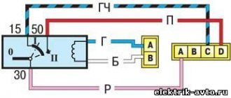
Pinout of the lighting control unit on Priora
This switching and control combined module has several functions and is used to turn on/off parking lights, headlights, select the desired light switching mode, turn on/off fog lights, adjust the brightness of the backlight combination, control the headlight range control, on/off and control light inside the cabin and instrument lighting. The module is connected to the vehicle’s on-board network via chip No. 1118-3724500.
The standard terminal pinout on a VAZ 2170 is as follows:
| G, 56b | To the gear motor for adjusting headlights |
| 58b | Output to backlight sources |
| 31 | Weight |
| Xz | +12 volts (from terminal 15 of the ignition switch) |
| 56 | To the relay for switching high and low headlights |
| 1,3 | From rear and front fog lights |
| 2,4 | To the rear and front fog lamp relays |
| 58 | To the size lamps |
| 30 | +12 V from terminal No. 30 of the ignition switch |
Electrical circuit diagram of the lighting control module of the VAZ 2170 (Priora).
Electrical circuit diagram of the lighting control module of the VAZ 2170 (Priora).
Module diagram.
Module pinout.
| Contact | Purpose |
| 1 | Indicator signal for turning on the rear fog lights |
| 2 | To the rear fog lamp relay |
| 30 | + 12 V (battery terminal 30) |
| 31 | Frame |
| 56 | To the headlights |
| 58 | To side lights |
| 58b | To sources of illumination of controls and instruments |
| G | To gear motors for headlight range control |
| Xz | + 12 V (terminal 15) |
| 3 | Warning signal for turning on fog lights |
| 4 | To the fog light relay |
| 56b | To the automatic headlight control system controller |
1 Symbols and index - white with light green backlight. 2 The position of the key or wheel is not fixed. 3 The color of the control indicators when not illuminated is uniform gray, turning to black; in the illuminated state: – yellow, for the rear fog lamp switch; – green for the front fog lamp switch. 4 Symbols on the electrical diagram: A1 – instrument lighting regulator; A2 – headlight range control switch; A3 – external lighting switch; A4 – front fog lamp switch; A5 – rear fog lamp switch; ХL1_ ХLn – LEDs for illuminating symbols (symbols); XL2 – LED illumination of the indicator of the outdoor lighting switch; XL3 – LED illumination of the control indicator for turning on the rear fog lights; XL4 – LED illumination of the indicator light for turning on the front fog lights.