The amount of electronics in modern cars is growing every year, which means that wires are practically everywhere. To ensure that they do not interfere with the operation and stylish interior of the car, they are tied and placed in special channels along the sides, ceiling and floor of the car, and covered on top with finishing panels, carpeting and upholstery.
These wiring harnesses run through narrow channels and are often subject to vibration and mechanical stress, which can cause one or more of them to fail. When this happens, all equipment that is powered by the damaged wire stops working. To cope with the problem, a car enthusiast must know how to test the wiring in a car with a multimeter to quickly and effectively restore its functionality.
Faulty or broken car wiring. DIY diagnostics
Problems with electrical wiring in a car occur quite often. For some drivers, this becomes a tragedy, so they urgently turn to the services of auto electricians. Although you can identify a broken wiring yourself with a minimum of effort. The only equipment you will need is a multimeter and basic knowledge of the electrical circuit of the machine.
Looking for a short circuit in the car
To quickly find a short circuit in your car, it is first recommended to check the safety elements and relays. Usually these two components make themselves felt when they fail. Having found these parts, you need to determine whether they belong to a specific node. In most cases, the description is on the fuse box cover. After which you can diagnose this node. A visual inspection of all the wires connected from the fuse box to the element will help here.
If you are unsuccessful in trying to identify a malfunction by external signs, you can use a multimeter. First of all, set it to resistance detection mode, then you need to disconnect the positive tolerance of the unit being diagnosed from the fuses themselves, as well as from the power source.
The next step is to connect one contact of the multimeter to the positive wire. The other contact is connected to ground. The absence of a short circuit will be indicated by the unit value on the device. If there is a problem, then the “plus” will touch the “minus” in a specific area.
Short circuit in the car
To answer the question of how to find a short circuit in a car, first check all the fuses and relays - as a rule, if there is a short circuit, one of them should fail. After finding such a fuse or relay, find out from the description (on the cover of the fuse box) which unit it belongs to. Next, start examining this unit - visually inspect all the wires running from it to the fuse box.
If external signs of a short circuit are not found in the car, then set the multimeter to resistance measurement mode, and then disconnect the “plus” of the unit being tested from the fuse box and from the device powered by it. Then connect one contact of the multimeter to the positive wire, the second contact to ground. If there is no short circuit, then the resistance on the multimeter will be equal to one. Otherwise, the “plus” somewhere touches the “minus”.
Read also: Chains for chainsaws types and sizes
Attempts to find a cliff
Checking a vehicle for current leakage with a multimeter involves similar manipulations as with a short circuit. The indicator of the presence of contact in this case will be the resistance measurement. If there is no contact, the resistance moves to infinity, and the device will display one. Contact presence - zero resistance.
Therefore, in order to quickly check for broken wiring in a car, it is necessary to connect our device to two contacts that are suspect in terms of breaks. Here also, the indicator of one indicates that there is a break.
To prevent a break in the future, do not twist the wires at random. For these purposes, there is a soldering iron and specially designed heat shrink. If there is a break in the terminal, be sure to clean it.
Multimeter and battery
It happens that the incorrect functionality of the battery is obvious. A multimeter comes to the rescue here too. Having picked it up and set it up to measure current, you need to:
Remember! Measurements are taken no earlier than an hour after the engine is turned off.
This means that if the capacity is, say, seventy-five A/hour, the corresponding load should be one hundred and fifty amperes. A voltage drop below nine indicates a battery malfunction. This may also indicate that the battery is undercharged. When you disconnect the load, the voltage usually returns to normal within seven seconds.
By the way, it is better to carry out wiring diagnostics armed with a diagram of the electrical equipment of your car.
Source
How to check a car battery with a multimeter
If you suspect that the battery is not working well, then again, a multimeter will help you. So, arm yourself with a multimeter configured to measure voltage (20V):
- Disconnect one terminal and connect the red contact to the positive and the black to the negative. Normal voltage should be between 12.4 - 12.8 Volts. It is important to take measurements at least an hour after stopping the engine.
- Measure the voltage under a load equal to twice the capacitance. For example, if the capacity is 75 Am/hour, then the load should be 150 Am. If the voltage drops below 9 Volts, it means something is wrong with your car’s battery (undercharging or failure). After disconnecting the load, the voltage should be restored within 5-10 seconds.
To repair home electrical wiring or a car's on-board network, you always need to know how to test wires with a multimeter. This device tests the integrity and serviceability of the cable; it can be used to check the insulation resistance and current voltage in the home electrical network. This is an indispensable meter for wiring and practical implementation of electrical projects.
How to check the wiring in a car for open circuits and short circuits?
Description of the process of checking car wiring for open circuits and short circuits: how electrics work, detection and diagnosis of faults. Video about electrical equipment in a car.
Problems with electrical wiring in a car often bother car owners, forcing them to look for an electrician or go to a car service center. Although you can check the wiring and detect a break yourself with a minimum of effort.
How does a car power line work?
An electrical circuit consisting of sensors and actuators has several paths for transmitting electricity, whose operation is often disrupted by a short circuit.
Sensors include light switches, temperature, oxygen and others, and drives include the engine, battery and other current consumers. This circuit or any other will function correctly as long as the wiring is intact. Damage to it can be caused by rodents, corrosion, mechanical damage, wear and tear from time of use, as well as unprofessional installation of this or that equipment.
Some automotive components are so tightly entangled in wires that it is very difficult to detect damage among them, including insulation.
Fuses protect all electrical circuits, with the exception of those on which the generator and starter depend. The power circuits of the most “gluttonous” energy consumers, such as headlights, heated seats and mirrors, and power windows, are switched via relays.
To find the problem, it is recommended to proceed in the following sequence:
Symptoms and Detection of Wiring Problems
The key cause of problems with wiring can be called damage to the insulation or malfunctions among electricity consumers, of which there are so many in modern cars.
As a result of active use, the process of wear, deformation and breakage of contacts occurs; the internal insulation may begin to melt, and therefore it will be necessary to find the faulty device that caused the short circuit. Also, the insulation in the car may be damaged due to improper routing of wires that touch the hot muffler pipe or are pinched by other elements.
Finally, the installation of additional equipment sometimes causes problems, especially the installation of parts in the area of the wheel arches or at the stern. If self-tapping screws are used for work, they can damage the insulation of the wires if installed improperly. Moreover, the motorist, in the absence of external damage, will not even know about the problem until the first “bells” appear.
The following symptoms will indicate the presence of problems in the electrical circuit:
In the first case, the problem is extremely dangerous, requiring the vehicle to be stopped immediately. This is necessary to prevent overheated wires from starting to melt all adjacent wiring, causing the fuse and relay to burn out.
Troubleshooting
Before checking the wiring, it is recommended to measure the voltage of the electrical circuit between different elements and electrical equipment as follows:
The displayed result should be compared with the values specified in the operating manual for the given machine model. After measuring the voltage, you can move on to searching for a short circuit, which will also require the above-mentioned devices, including a test lamp, which, if there are no problems with the wiring, should not light up. If there is a short circuit, the tester will give a corresponding sound signal.
A shorted wiring usually indicates a problem in one of two places: in the consumer equipment or in one or more wires. Before taking measurements, the fuses are removed from the area being tested, after which a probe is installed on the terminals of the fuse element, where a zero reading will indicate a short circuit.
If, after touching the wires, the device shows the appearance of voltage on the line, then the problem really lies in the wires that require replacement.
The next step is to check the grounding, violation of which causes corrosion or oxidation of metal parts, as well as loosening of fasteners. To troubleshoot you will need:
It is also recommended to compare the obtained result with the factory requirements according to the operating manual. If there is a large discrepancy in the indicators, it will be necessary to strip the metal at the grounding site and check the strength of the fastening for restoration.
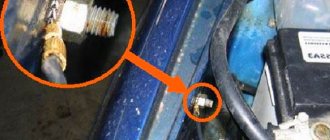
Another problem area is the wire connection unit, where in addition to a break, damaged insulation and violation of the integrity of the power line, the contacts oxidize, which can be determined by visual inspection. In this case, you will have to solder wires with connectors in the damaged area.
If the motorist does not have short circuit detection equipment, he can use a smaller fuse than the standard one. One or a pair of strands of a car wire with the insulation removed from it is wound around the fuse, the entire wiring is conditionally divided into parts, separating the connections, and they begin to search for the fragment where the wire causes a short circuit.
So, on modern models the wiring is called front and rear, so if the fuse blows with the front wiring disconnected, the problem should be looked for from the front.
The separator for the wires can be switches or relays, that is, if a fuse burns out as a result of activating one or another key, we can talk about a short circuit. Then you should remove the relay in the electrical circuit that turns on when you press the key, and then check again. In this way, it is possible to determine in which part the short circuit occurs.
The search for the so-called “short”, as professional electricians call a short circuit, is mainly carried out by elimination, which is a very time-consuming task. The motorist will need to sequentially turn off all possible consumers of electricity on the corresponding electrical circuit, which can be learned from the car's electrical circuit.
Since some wires are located in hard-to-reach places, for example, under a dashboard, you should start not by inspecting the general wiring, but by excluding consumers.
To detect the equipment where the short circuit has occurred, the power line in question must be energized. Due to the fact that the fuse instantly burns out when the circuit is activated, before starting the search it is necessary to connect a separate powerful consumer of electricity to the line to reduce the high short circuit current and prevent the wiring from catching fire.
Conclusion
Breakdowns and problems with a car can happen at any time, including when the driver is unavailable for professional help. If during a trip outside the city, in nature or on a highway far from populated areas, the driver encounters a short circuit, understanding the electrical circuit and the steps in detection will help the driver safely get to the technical assistance center.
Video about electrical equipment in a car:
Source
How to repair car electrical wiring?
Faulty vehicle wiring leads to serious problems during the operation of the car - from incorrect operation of sensors and devices, on-board computer and automation to complete failure of expensive electrical equipment. Remember that a short circuit in the on-board circuits can lead to a fire in the vehicle. Therefore, faults in electrical equipment and electrical equipment should be eliminated immediately when they are detected - there is no need to put off repair work “on the back burner”.
You can repair car electrical wiring either yourself or at a car service center. The main difficulty lies in finding faults - breaks, failed relays, fuses and blocks, breakdowns of individual elements and auto electrical devices.
Common machine electrical faults
Auto electrics include various systems, parts, devices and elements of the vehicle - the ignition system, battery and generator, on-board computer circuits, fuses, sensors, relay blocks, various electronic sensors, auto lights, as well as auto electronics - climate system, audio system, automation and systems security. It is necessary to take into account the peculiarities of automotive electrical wiring in order to quickly find and eliminate a malfunction in the on-board network.
Common electrical problems include:
How to check wiring
You can diagnose electrical equipment using a voltmeter, ohmmeter or multimeter, or special diagnostic stands. Computer diagnostics are also carried out, during which error codes and main indicators of the machine’s on-board network are read. To independently check circuits and troubleshoot electrical faults, one multimeter or signal lamp is enough.
We use a multimeter
Checking the voltage
Before checking the wiring in the car, it is necessary to measure the voltage of the electrical circuit between individual components and electrical equipment. You can call like this:
If a certain value appears on the device display, then there is voltage in this section of the electrical circuit. You can compare the values with those required according to the vehicle's owner's manual.
Looking for a short circuit
After measuring the voltage, search for short circuits. This will require either a multimeter or a pilot light. As for the lamp, if the wiring is in good condition and there is no short circuit, it should not light up.
A short circuit in the wiring, as well as a lack of voltage (zero or infinite resistance in the electrical circuit), indicates a malfunction in one of 2 components:
How to prepare for testing car wires
Before checking the wiring in your car with a multimeter, you will need to prepare a regular digital household multimeter, test leads, a long wire and alligator clips. You will also need to have a vehicle repair manual and a wiring diagram.
Having an electrical diagram of the circuit will greatly simplify diagnostics and help identify loads, wires, switches and control devices in the circuit. Thanks to this, the user will be able to understand how the current should flow in the circuit, how it is protected, and also in what state it is usually closed or open. If there is no diagram, you can buy it or download it from the Internet for a specific car brand.
Important! When studying the circuit, you will need to pay special attention to the connectors, connections, switches and components in the circuit where there is a possible break. To avoid confusion, identify wires by color and the terminals, switches or loads to which they are connected. Carefully disconnect the connectors so as not to damage them. If possible, disconnect the sensor connectors from the rear side or from the wire side.
Checking relays and fuses
According to the Auto Repair Manual, it is determined which fuse or relay is associated with the non-working equipment. If there are several non-working components, the common points in the circuit are determined from the connection diagram. This will significantly narrow down the troubleshooting area.
Check sequence:
- Turn off the engine.
- Open the cover of the fuse compartment, which is usually located under the steering wheel or under the hood of the car, and is indicated by a small electrical symbol.
- There is a guide on the fuse box cover to help you determine the function of each and locate it.
- Using the small pliers supplied with the block, release the fuse being tested without any effort.
- If, upon external inspection, a black spot is noticed on the numbers or a broken thread, then the fuse has blown and must be replaced.
For a more accurate check, use a multimeter in dial mode. If the fuse does not ring, it is faulty. Replace the blown fuse with a new one with similar characteristics.
Visual inspection of wiring
Before testing the wires with a multimeter in the car, perform a visual inspection of the wiring. In order to find a damaged wire, open the non-working equipment of the car and find the power wires. In many cases, this will require removing interior trim panels. If the wires are enclosed in a flexible plastic tube, carefully remove it so that they can be inspected. If a wire is found to have damaged insulation, it will need to be replaced.
Car electrical wiring repair
You can check and restore the car's electrical wiring yourself or at a car service center. After identifying faulty areas where there is damage to the wires, a short circuit or a break, they are soldered or completely replaced. Conventional twisting followed by crimping is not a full-fledged repair, but only a temporary measure - take this into account if you do not have the opportunity to solder the break points.
Mounting blocks located in the engine compartment are also considered a vulnerable element of a car's electrical system. Due to the destructive effects of temperature and moisture changes, damage to the protective coating and subsequent defects in tracks, connectors for connecting wiring harnesses, relays, and capacitors are possible. Repair of mounting blocks, consisting of circuit boards, fuses and electrical components, includes soldering to restore tracks and coating with a special protective varnish, as well as replacement of faulty elements and wiring, connectors, cleaning contact groups from dirt and oxidation.
Checking the fuse box
If you're experiencing electrical component failures in your vehicle, the first place to look for problems is the fuse box. Most cars have several types of fuses. Fuses are located in the engine compartment, under the dashboard or on the dashboard.
The engine compartment fuse box usually contains large fuses for the alternator, electric fans, or starter. The fuse panel inside usually contains smaller fuses for things like brake lights, clock and radio.
Of course, there is a diagram according to which you can understand which fuse is responsible for which element. Find the fuse for the component you are having trouble with and remove it. If the glass or plastic appears dark, the fuse has probably blown and needs to be replaced.
If it turns out that the electrical problem is not caused by your fuse blowing, you can move on to checking the component itself. Make sure it is connected, moves freely, and is not burnt or melted.
Many of your car's electrical components can be tested without removal - by measuring the resistance value between the contacts. If you have an ohmmeter and your car's repair manual, you can check the component.
Replacing car wiring
When replacing wiring in a car, be sure to turn off the power, including disconnecting the battery. Of course, this is not a precaution against electric shock, but protection of the vehicle’s electrical equipment from possible short circuits that may occur during repair work.
Sometimes the replacement can be completed in 10-15 minutes - for example, if the wires of the “battery-generator” supply circuit are damaged. If the integrity of the wiring in the cabin is damaged, there are problems with grounding, or a short circuit in the on-board computer circuit, then the work will take much more time. And the main thing here is not to make a mistake, since incorrectly connecting the wires (for example, if the polarity is reversed) can cause a short circuit, damage to expensive electrical equipment and even a fire. If you do not have experience in electrical engineering and electrical installation work, it is better to contact a specialized service for the services of a professional auto electrician.
Source
Relay test
Another item that needs checking if you have electrical problems is the relay of this component. Relays are used in high power appliances and are electrically activated switches. When you turn on your car, several components turn on, such as the fuel pump, computer, and electric fans.
The switch in your ignition can activate multiple relays, turning all the peripheral equipment without running full power through the ignition switch. Relays can also deteriorate over time and cause electrical problems.
The best way to test the relay is to have a working replacement or listen carefully to how the relay operates while turning on the device. You should feel light pressure and hear a soft click when the relay turns on.
How to test the wiring in a car yourself with a multimeter
People have long lived surrounded by electrical appliances, which have quietly entered the life of every person since childhood. Electronic watches, electric kettles, telephones, computers, cars are indispensable human assistants in everyday life and at work. But sometimes devices break down and you have to check and repair them. There is nothing difficult about this if you know how to use measuring instruments and know, for example, how to test the wiring in a car with a multimeter or how to check the integrity of an electrical circuit.
What you need to know about the device to connect wires
dialing mode
If you plan to test the wiring in your apartment, you need to know several fundamentally important facts about multimeters. First of all, it is worth noting that you can check the wire with the simplest device. An inexpensive Chinese model with minimal capabilities is quite suitable.
But at the same time, it is most convenient to use a device that has the dialing function itself. In order to set the device handle to the appropriate position, you need to turn it in the direction of the diode icon (as an option, an image of a sound wave can additionally be applied). This means that when checking the integrity of the wire, a sound signal will sound when the contacts are closed.
But the presence of sound is completely optional for testing wires with a multimeter. The fact that the circuit is broken will be indicated by a unit on the display, indicating that the resistance level between the probes is higher than the measurement limit. If there is no damage in the area under study, the resistance value will be displayed on the screen, which ideally should tend to zero (subject to operation in short-distance household networks).
General information
If a connection is found, then if there is a built-in speaker, the device emits a sound signal. This is where the term “call” comes from. The device rings if there is a connection. A multimeter can also indicate that there is no connection between elements and helps determine a short circuit. Using the tester, all kinds of radio components are checked: resistors, transistors, diodes, relays, capacitors, and so on.
Conductor continuity is based on Ohm's law for a section of an electrical circuit. Ohm's law states that the resistance of an element is equal to the ratio of the applied voltage to the magnitude of the current in a section of the electrical network. Resistance is measured in Ohms. A resistance of one Ohm indicates that a current equal to one Ampere flows through the conductor at a given voltage of one Volt. Based on the calculated data on resistance, conclusions are drawn about the results of the call.
That is, a certain voltage is set on the multimeter, and the current value is determined using the instrument scale and the resistance is calculated. In other words, the multimeter is a voltage source and an ammeter to measure the resulting current.
Setting up and preparing the multimeter
To use the multimeter correctly, you need to configure it. This means that you need to select the value to be measured and the limit of its operation, that is, the value beyond which it will not go.
Symbols on the front panel of the meter
A multimeter can be used to check various electrical quantities: current, voltage, resistance, frequency. It is also used to test the performance of various radio elements: resistors, capacitors, diodes and transistors. The very part of the word “multiple” implies the presence of several types of measurements. To select these types, there is a knob on the front panel of the tester, by turning which you can select the required value.
There is a higher class type of multimeter, for example, Agilent, in which the selection of measurement values is made not with a rotary knob, but with buttons. To select a value, simply click on the button corresponding to this value.
In most cases, the symbols depicted on the body of the multimeter represent designations of electrical quantities accepted in physics or conventional graphic designations of radioelements intended for testing . On the front panel you can find the following symbols:
- U - voltage symbol;
- V - stands for volts, this is also a measure of voltage;
- I is the current; when you set the knob to this designation, the current strength will be measured;
- A - amperes, a measure of current strength;
- Ω, R - symbol of resistance;
- Ohm is a measure of resistance, Ohms;
- -| |- - this icon indicates a capacitor, the multimeter will measure its capacitance;
- Diodes and transistors are also marked on the tester body with their symbols.
But not only the measured values are indicated on the front panel of the tester: the holes for connecting the probes also have their own designations. One of the meter slots will always be occupied by the black probe. This is a common hole, it is usually marked with the inscription COM, which means “common”. In addition to it, the multimeter has two or three working holes, designed respectively for measuring voltage, low current and high current.
The socket marked U, Ω, Hz is intended for measuring resistance, voltage and frequency, as well as for testing various radio elements. You also need to install a probe here to test wires and cables for breaks.
The hole marked mA (mA) is used to test low currents (up to 1 ampere), and the hole marked A (10 A) is needed to measure high amperages.
Also next to the voltage and current icons there are symbols
or -. This indicates the nature of the measured quantity: direct or alternating current or voltage.
Limits of measured values
In addition to designations of the values of the parameters being tested, designations of measurement limits are printed on the front panel of the multimeter. In more advanced equipment, these inscriptions are not present, since the tester electronics itself selects the limit based on the signal supplied to it at the input. However, most multimeters require manual adjustment of measurement limits.
Read also: DIY small-sized gearbox
Typically, limits are given by numbers that are multiples of 2: 2, 20, 200... Thus, when choosing a limit, you should be guided by the rule: choose a limit higher than the one being measured, but of the same order. For example, to measure the voltage in a home electrical network (in an outlet), you need to select the AC voltage measurement mode and the measurement limit of 2000 volts. And to test the wires with a multimeter, you need to select the resistance mode and the minimum measurement limit of 2 ohms. However, long cables require a higher measurement limit of 20 ohms. Additionally, you can turn on the button with a sound signal that sounds when a short circuit occurs (circuit presence).
Connecting the tester
To check the parameters of electrical circuits and the continuity of wires and cables with a multimeter, you must correctly connect the meter to the circuit being tested. When checking for circuit integrity, the required area between the meter leads is checked. Therefore, the tester is connected to the terminals of the circuit. If voltage is being measured, the multimeter must be connected in parallel to the section where the voltage is being tested.
When measuring current, the multimeter must be connected in series to the open circuit of the circuit being tested, for example, between the power supply terminal and the load terminal.
Device structure
Devices may differ in appearance, but multimeters are fundamentally divided into analog devices and digital devices.
Analogue devices are already gradually being replaced from the market by digital ones, but in the homes of many home craftsmen you can still find analog devices.
Such devices are equipped with an indicator screen with a scale and arrow. The advantage of these models is the clarity of display of measurements. The deflection of the needle is visually easier to assess than the flashing of numbers on the electronic display of digital instruments. Often, when making a call, it is necessary to evaluate approximate resistance indicators or, in general, its presence or presence, so analog devices are suitable for most practical work.
Digital multimeters have more complex electronics and a digital display. This type of device is used mainly in production and industry.
The housings of all multimeters have outputs for two probes. These are two insulated wires ending in needle-like metal tips. In some cases, special clips, so-called “crocodiles,” are put on the nozzles. When choosing a device, you need to pay special attention to the quality of the probes. The correctness of measurements depends on them.
The wires must be flexible with strong soldering and fit well into the device sockets. It often happens that outwardly spectacular probes are of unsatisfactory quality and have poor technical characteristics.
Operating principle
The analog type of the device does not require its own power supply . Its operating principle is the same as that of an ammeter, and an analog device works best in the range of radio waves and electromagnetic fields. There are induction coils inside the device body, and when the probes touch the conductor, a current begins to form in the coils. The created magnetic field deflects the indicator needle to a certain angle. The magnitude of this angle depends on the strength of the current generated, and the arrow on the drawn scale indicates the measurement value.
What is a multimeter
A multimeter device is used mainly for measuring voltage, current and resistance in an electrical circuit and in its individual sections. Simply put, the device in one shell has a voltmeter, ammeter and ohmmeter.
What does the device look like?
Depending on the device and the number of additional options, it is used to study the integrity of an electrical circuit, monitor and measure the characteristics of its components.
The device can also measure direct and alternating current.
When measuring each characteristic (current, voltage, resistance, etc.), you first need to:
- visually determine the measurement scale. So, for a battery it will be 1.5V, 7.5V, 12V and higher. The value must be taken more than necessary. Simply put, this is a “strength reserve” so as not to break the device;
Multimeter design
- choose the correct measuring direction. In this case, it is necessary to move the device pointer to the required position, based on the generally accepted parameters indicated on the body;
- connect the probes correctly. For any type of measurement, the negative (black) probe is inserted into the common socket (COM), the positive one is connected into the socket required for a specific type of measurement.
Continuity of wires
Before starting any measuring work, it is imperative to check the serviceability of the tester itself.
It happens that the measuring system itself is faulty. To check, the ends of the probes of the measuring device are in contact. If the device is operational, the indicator will display zero or deviate slightly. A slight deviation indicates that the probes and terminals have their own small resistance.
If the multimeter has a sound signal, then the device is set to buzzer mode. This is done by placing the switch on the corresponding icon on the tester body.
The probes are brought to the ends of the part being tested.
Possible tester behavior options:
When taking measurements with a multimeter, do not allow the human body to come into contact with probes and wires where there is no insulation.
Sequence of actions when calling
- Before you test the circuit with a multimeter, you need to turn the handle of the device to the desired position.
- Install the ends (measuring leads) into the appropriate sockets. The black wire goes into the socket marked COM (sometimes it can be marked with “*” or a ground sign), and the red wire goes into the socket where the Ω sign is indicated (sometimes it can be marked with an R sign). It is worth noting that the Ω sign can be applied either separately or in combination with the designations of other units of measurement (V, mA). This is the correct position of the test leads, which will allow you to maintain polarity when making further measurements. Although if only the integrity of the wires is checked, their relative position will not affect the result obtained.
- Turn on the device. A separate button may be provided for this, or activation may occur automatically when the knob is turned to the desired position when selecting measurement limits or operating modes.
- Connect the measuring ends to each other. If a signal sounds, it means that the device is operational and ready for use.
- Take the cable or wire being tested (its ends must first be stripped of insulation, stripped to a metallic shine, and dirt and oxides removed from the surface). Touch the test leads to the exposed areas of the conductor.
- In case of continuity, a signal will sound, and the device readings will either be 0 or indicate the resistance value. If the display shows 1 and there is no beep, the tested conductor is broken.
Troubleshooting in a car's electrical circuit
If some component in the car does not work, then first of all you need to check the electrical circuit. There are no particular differences between how to test different wires in different cars with a multimeter, except for the high-voltage cable.
First, make sure that there is voltage in the circuit of the non-working unit:
If the tester indicator shows the presence of voltage, it means the wire is intact. By analogy, all wires of the node are called. If the wire is damaged, the multimeter scale shows zero.
It must be taken into account that in some areas of the car voltage is supplied only when the ignition key is turned on.
When the voltage check is completed, the current value is checked. The device is switched to ammeter mode, the switch selects a measurement range of up to ten amperes. All vehicle devices must be turned off and the tester must be properly connected to the vehicle's electrical network. To do this, a multimeter is connected between the positive terminal of the battery and the unit being tested. The device screen should display the found current value; it should correspond to the consumption of constantly switched on devices of the machine. If the current value exceeds the norm, a conclusion is drawn about its leakage.
In this case, they begin checking devices that are not included in the standard equipment of the car, and places where wiring is part of moving mechanical components.
Experienced craftsmen identify areas with a drop in current, focusing on the readings of a multimeter with the fuses removed one by one. Then check for sparking at the contacts.
If a misbehaving wire is detected, it is ringed to check its integrity, and then its resistance is measured.
One of the answers to the question of how to test wires with a multimeter is to measure the resistance of each of the wires of the node. The rating is applied to the braid, and a tester is connected to the wire in ohmmeter mode. Typically, the range of resistance values for automotive wiring ranges from 3.5 to 9.9 kOhm. The difference between the measured element and the norm should not be more than four kiloohms.
How to detect a short circuit
Step-by-step instructions on how to determine a short circuit with a multimeter:
- When electrical devices and the network are turned off, you need to measure the circuit resistance in individual nodes. If possible, it is advisable to use a wiring diagram for the electrical supply of a house or apartment. If a lot of resistance is shown, then this section is working. And in places with a short circuit, the resistance will be 0. However, the device can also display a high resistance indicator, mainly if there is a large distance to the short circuit. For this option, it is advisable to use a megohmmeter;
You may be interested in this Metal detector for wiring
Insulation tester megohmmeter
- if there are no such devices, then you can use a test lamp with an independent current source. You can equip a regular flashlight with probes for this (the light bulb should work when the pins are connected to each other). By closing the required network cores one after another at the connections of the distribution boxes, a short circuit can be detected by a working lamp;
- remove the damaged cable. There is no need to perform spot installation of electrical wiring. Firstly, hidden wiring is located under the facing material, which means additional costs for installation work. Secondly, it is recommended to replace the entire damaged cable, since the short circuit may occur again. It is advisable to place the new cable behind the baseboard. Using a special box, connect it to an outlet.
Checking the wiring through the socket
How to ring electrical wiring
This process is mainly done using a multimeter. This device is quite inexpensive, so it is advisable to have it in your tool kit.
The easiest option for dialing is to perform it at the installation stage. How to do it correctly:
- check the wire for the appropriateness of the declared power. The cross-section of the wire will be equal to the total power of the electrical appliances that will be used in this network;
- check the cable insulation for integrity. This can be done visually;
- measure the insulation resistance with a megohmmeter. For an electrical circuit with a standard voltage of 220 V, the resistance should not exceed 0.5–1 MOhm;
- correctly check the network under maximum load. To do this, you need to turn on all the devices at once.
Checking circuit continuity
You can also test the wiring using a socket. Move the range knob to the AC voltage measurement position. It is necessary to set the indicator to 750 V. The probes of the device are connected to the holes in the socket. The voltage should show 220 V. The maximum error is 10%. If it exceeds the permissible deviation, then it is necessary to use surge protectors to connect household appliances.
How to check circuit continuity
To test the integrity of electrical wiring, you must use a digital multimeter operating in resistance mode. When carrying out the test, you need to make a closed circuit, which consists of the device itself, two measuring “probes” and the wire being tested.
You may be interested in How to check with an indicator screwdriver
Continuity from battery
Attention! During operation, a small electric current is passed through the test area, and the device will recognize the indicator of its internal resistance. This option is suitable for those who do not have special electrical skills.
How to ring wires in a car
Step by step process:
- Use the handle to set the device to voltage measurement mode;
- Connect the end of the device to the ground of the car or to the minus of the battery. A distinctive feature of the power supply pair in the machine will be that the negative wire is either very short or completely absent;
- The second probe touches the supply wire. It must be disconnected from the device clamp.