04/10/2021 3,169 Sensors
Author: Ivan Baranov
The braking system of modern cars is equipped with an anti-lock braking system, which reduces the braking distance and allows you to drive the car in a sharp deceleration mode. To check the ABS sensor, you can use a tester, an oscilloscope, or perform diagnostics without instruments.
[Hide]
Symptoms of a problem
To monitor the operation of the system, there is a yellow or orange indicator light. In normal conditions, when the ignition is turned on, a lamp on the instrument cluster is activated, then self-diagnosis of system elements is carried out and the icon automatically goes out.
Signs of breakdown of ABS system elements:
- turning on the system warning lamp while driving;
- stable wheel locking during heavy braking;
- absence of sounds indicating ABS operation (brake pedal vibration);
- the appearance in the memory of the electronic system of error codes related to the ABS.
If signs of ABS malfunction appear, operation of the vehicle is prohibited. The brakes, designed to work together with the anti-lock braking system, do not work correctly when it is turned off.
Sensor types
There are two types of sensors on cars:
- passive sensor built on the basis of a coil;
- active sensor that uses the Hall effect.
The passive sensor turns on after the start of movement and reads data from the toothed pulse ring. The passage of a tooth past the device causes the generation of a current pulse, which is read by the control unit. The sensors start working at speeds above 5 km/h and do not respond to contamination.
The active sensor consists of electronic components and a permanent magnet, which is mounted on the hub. When the magnet rotates in the device, a potential difference arises, which is formed into a microcircuit control signal. The information is then sent to the block. Sensors of this design are rare and cannot be repaired.
Inductive passive sensor design
In many cars (both domestic and imported), a passive induction sensor is used as an ABS sensor, which is a coil wound on a magnetic core. It is installed opposite a toothed disk mounted on the hub axis. When the vehicle moves, an alternating voltage appears at the sensor terminals, the frequency of which depends on the speed of rotation of the wheel.
On a note! We have already written about how to check the active Hall sensor, which is used in some car models as an ABS sensor.
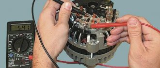
Checking ABS sensors with a tester
The car owner can check the condition of the sensors independently. This will require a few minutes of time and a simple tester. In order to check the sensor with a multimeter, you need to know the resistance value of a working coil. The measurement is made by removing the device or by disconnecting the plug connector.
Self-testing is carried out according to the following algorithm:
- Place the car on a level surface or a lift. Ensure reliable fixation against accidental movement.
- To make access to the sensor easier, it is recommended to remove the wheel.
- The wire is laid along the wheel arch and connected to the general wiring using a plug, which must be carefully disconnected. If the plug is covered with a layer of dirt, then it must be removed and the connector pads should be wiped with a clean rag. If the rear wheel sensors are checked, the connecting plugs are located in the vehicle interior. To access the plug, you need to fold back the seat cushion and peel back the carpet. On some cars, you will need to peel back the soundproofing mats located under the carpet.
- Switch the multimeter to ohmmeter operating mode.
- Connect the sensor leads to the multimeter probes and measure the resistance. Compare the value with the standard values available in the operating instructions. If such information is not available, then the readings are taken from reference literature. Usually a resistance of 0.5-2 kOhm is considered normal.
- Ring the sensor wiring harness to check for a short circuit.
- Check the operation of the sensor. To do this, rotate the wheel and look at the ohmmeter readings. Depending on the rotation speed, the resistance will change.
- Switch the measuring device to the “voltmeter” operating mode.
- Rotate the wheel at a frequency of about 1 rpm, while checking the voltage value. According to standards, it should be in the range of 0.25-0.5 Volts. As the speed increases, the voltage increases.
- Check all sensors using the procedure described above. It must be remembered that the devices on the front and rear axles differ in design and have different resistance.
Measuring resistance with a multimeter
Based on a certain resistance value, you can draw a conclusion about the state of the sensor:
- the resistance is below the permissible level - sensor malfunction;
- the resistance is close to or equal to zero—turn-to-turn short circuit in the sensor coil;
- variable resistance that changes when the position of the wiring harness changes - breaks in the wires inside the cable;
- the resistance value tends to infinity - wire or coil breaks.
If it was not possible to find out the resistance value of a working ABS sensor, you need to measure the remaining devices. A device with parameters noticeably different from the others is most likely the cause of the ABS malfunction.
Additionally, you should use a tester to check the integrity of the wiring harness from the sensor plug to the block on the control unit:
- Disconnect the connectors from the sensors and control unit.
- Find information about the pinout of the control unit plug. The pinout can be found by the valve body model, which is printed on the housing identification plate.
- Ring the wiring harnesses.
Features of the Opel Vectra sensor
Now let's go over the features of the Opel Vectra. And the main one lies in the fact that this sensor is made in the form of a ring and is mounted on the hub. Therefore, it is not difficult to check it again using a multimeter, but replacing it in case of damage is difficult, since you will have to remove the hub.
In general, by simply measuring the resistance, you can assess the condition of any ABS sensor, as well as its wiring.
Whatever element is used on the car, its resistance will vary in the range of 1.2-1.8 kOhm.
One of the main conditions for diagnostics is not only the resistance value, but the same resistance reading on all sensors.
Label: Sensors
How to check using an oscilloscope and adapter
Testing with an oscilloscope allows you to more accurately test the sensor for functionality. The oscilloscope shows graphs of changes in the signal generated by the device. The sensor can supply pulses that comply with the standards, but the amplitude of the signal will be incorrect and will cause an ABS operation error. The test is performed on the car, without removing the sensor.
In order to check the ABS sensor with an oscilloscope, you must:
- Disconnect the sensor plug by analogy with the procedure used when measuring parameters with a tester.
- Connect an oscilloscope or oscilloscope to the sensor pins.
- Start rotating the hub through the wheel or other method at a frequency of 2-3 rpm.
- Record the signal oscillation curve.
- Carry out a similar procedure with the sensor located on the other side of the axis.
The serviceability of the sensor is indicated by:
- identical amplitude of oscillations of signals from sensors located on the left and right sides of the same axis;
- uniformity of the curve, without noticeable lateral deviations;
- amplitude stability in height, which should not exceed 0.5 volts.
Another way to measure parameters is to connect a laptop equipped with a special adapter. The device connects to a USB port and transmits signals to the corresponding software.
Sample USB Oscilloscope
The oscilloscope and adapter are highly specialized devices and are rarely used for personal use. The equipment is used in service stations.
Design nuances of Lada "Priora", "Kalina"
Now let’s figure out a little how to diagnose and replace Lada cars of the Priora and Kalina models. These cars were taken as an example because they use drum brakes at the rear, and above we looked at how work is carried out with sensors that work with disc mechanisms.
Checking the sensors on Kalina or Priora is completely identical to those described. But this sensor still needs to be found. The element is installed in the rear wall of the hub, and the impulse ring is located inside the mechanism, under the drum.
Therefore, in order to assess its condition, you will have to remove the drum from the car, and immediately under it you will see the ring, as well as the protruding part of the sensor, which passes through the technological hole in the brake pad.
That is, by checking the condition of the ring, you can immediately look at and clean the sensor itself from dirt. And then we measure the resistance of the sensor and the entire circuit up to the “brains”.
Checking the sensor without instruments
The most crude way to check the health of the sensor is to test the magnetic field created during operation of the device. To do this, a steel object is applied to the sensor, which should be attracted when the ignition is turned on.
It is possible to visually inspect the device for cracks in the housing or noticeable breaks and oxidation in the wiring. It is recommended to inspect the plug and the condition of the contacts in it; oxidation is the cause of deterioration in signal conductivity.
How to fix problems
After checking with instruments and identifying the faulty unit, you can begin repairs. Some owners repair the sensors by replacing the wiring harness or rewinding the coil.
Sensor failure
A faulty passive type sensor can be repaired yourself:
- Remove the sensor from the hub. The fastening bolt often becomes sour, so you should unscrew it carefully. For removal it is allowed to use WD40 type fluid.
- Remove the protective coil housing. Removal is done with a file. The cut should be done extremely carefully so as not to damage the housing and winding.
- Remove the protective film from the winding by prying it off with a sharp knife.
- Carefully unwind the wire from the spool. During the removal process, the version of a conductor break is confirmed. As a result, you will be left with an empty ferrite core, resembling a spool of thread in shape.
- Wind a new winding. Copper wire from the coils of common relays of the RES-8 type can be used as a conductor. Winding can be done using a drill with smooth speed control. Be careful as breaking the wire will return you to the start. It is recommended to wind the conductor to the top level of the coil.
- Check resistance. Most coils have a value in the range of 0.9-1.2 kOhm. To clarify, it is recommended to measure the parameter on a known-good sensor located on the opposite side of the axis. The resistance is adjusted by unwinding the excess wire. If the reading is low, you will need to use another wire or re-wind. Secure the wire from unraveling with tape or other adhesive tape.
- Solder the wires to the coil terminals that serve as a connection between the winding and the harness. For outputs, it is recommended to use multi-core insulated cable, which has increased strength.
- Install the coil into the old housing. If it received significant damage when disassembling the device, then the coil is filled with epoxy resin. To do this, the part is located in a metal container of a suitable size, for example, a capacitor housing. The air gap between the coil and the glass is carefully filled with resin. When pouring, it is advisable to avoid large air voids. After the resin has completely hardened, the body is removed.
- Reinstall the sensor mount, securing it with epoxy resin. Conduct a visual inspection of the product for cracks and voids in the insulation. Detected defects are filled with resin.
- Place the repaired sensor in its original place and check the functionality of the ABS system. When installing the device, it may be necessary to modify the resulting body, which is done with a file and sandpaper. The field installed sensor should have a gap between the coil and the toothed ring within 0.9-1.1 mm. When reducing the gap, it is recommended to bring it up to standard by installing gaskets.
Cut body
Repaired sensor assembly
Sensor with holder removed
Making a resin body
You need to drive the car for a while, checking the brakes at different speeds. There are cases when the ABS spontaneously activates at certain wheel speeds - usually just before stopping. Then you will need to search for the gap, adjusting it with shims or sharpening the sensor body.
Another repair option is to install a modified crankshaft position sensor from domestic cars:
- Remove the “original” sensor and modify the body of the “donor” part. Most often, this role is played by the DPKV from the ZMZ-406 engine, which has a resistance within 800 Ohms. When modifying, you should strive to ensure a parallel arrangement of the core with the wound coil and the toothed ring mounted on the axis. The gap between the sensor and the ring should be within 0.2-0.3 mm.
- Test the operation of the device. On some Japanese-made cars, the ABS lamp may turn on periodically. The situation is corrected by changing the connection of the harness contacts.
Both options for repairing the sensor require perseverance and the ability to work with various tools from the owner. If the car user doubts his abilities, it is recommended to purchase a new device or find the product at a car dismantling site.
Wiring problem
If the problem of sensor loss of functionality lies in the wiring, then it can be replaced:
- Unscrew the sensor mount to the wheel hub.
- Disconnect the wire plug.
- Remove the sensor along with the wire. This will require removing the mounting brackets installed on the wiring.
- Measure the installation distances of the brackets. It is recommended to draw a diagram and photograph the factory location of the fasteners.
- Cut the sensor from the wire, leaving some extra length for soldering.
- Check the integrity of the remaining cable on the sensor. If the section is intact, then you can begin installing a new wiring segment.
- Remove all protective covers and fastenings from the old cable.
- Select a wire with a suitable outer diameter and cross-section.
- Install the previously removed protection and fastening elements onto the new harness. To facilitate assembly, it is recommended to use a soap solution.
- Solder the sensor and plug into place.
- Carefully isolate the joint. The accuracy of operation and service life of the repaired part depend on the tightness of the connection.
- Reinstall the sensor, check the functionality of the ABS system, and make sure there are no errors during operation.
Dismantled sensor with harness
There is a section of wire in front of the sensor that needs to be left
Removed fasteners and covers
Repaired wire
Using a laptop as an oscilloscope
From a technical point of view, professionals consider using an oscilloscope to be the most correct method for checking ABS sensors. However, the device is expensive, and it makes no sense to purchase it just to test sensors. Well, if you have a laptop, then using it as an oscilloscope is quite simple. First, we make a measuring cord to connect the sensor connector to the microphone input. To do this, you will need a 3.5 mm mini jack plug, two resistors and a couple of pieces of wire of a suitable length. The cash costs for purchasing the necessary components will not exceed 50 rubles. We solder the wires to the contacts of the mini-jack, and install a resistive divider in the gap (to protect the sound card) according to the diagram below.
Then everything is simple:
- We install a special Oscilloscope program on the laptop (for example, Winscope or Avangard).
- We connect the wires to the ABS sensor connector, and the plug to the microphone input.
- Rotate the wheel hub.
- If the sensor is working properly, we see a clear sinusoidal signal on the screen.
On a note! If you don't have an assistant, it will be very difficult to rotate the wheel and watch the laptop screen at the same time. For convenience, we recommend using the recording function. By turning on the playback mode (after performing the test described above), you will be able to see the test results.