Most owners of a Lada 4×4 (Niva) car are thinking about how to improve the factory characteristics of the model, and one of the most popular procedures for tuning a car is installing an additional fan.
In case of frequent off-road trips, the car engine is subjected to strong heating, which standard equipment cannot cope with; the same thing happens during long-term use during the hot season, especially in the southern regions.
If the engine overheats, repairs will be quite expensive, and an additional cooling fan will help avoid this risk. After installing this element, the Niva can be used in the harshest conditions without fear that the internal combustion engine will “boil”.
Carburetor Features
When modernizing the Niva in 1994, it was decided to install a Solex carburetor on it. Before this, a unit called Ozone was used. Which one is better? This question interests many owners.
Ozone is equipped with an old style breaker. In addition, it does not have a vacuum corrector. Solex does not have a microswitch for the economizer. This negatively affects the purity of the exhaust, and also partly on fuel consumption. Both carburetors have both their advantages and disadvantages. However, VAZ engineers opt for Solex, as a more modern model. In turn, many owners of cars with this carburetor often complain about its incorrect operation. Experts explain that this is caused primarily by the use of low quality fuel. In addition, troubles can arise for those who rarely change the fuel or air filter, and also do not clean the carburetor of oil soot entering through the ventilation system. Some owners of old Niva cars equipped with Ozone decided to install Solex instead. And they don’t regret it.
Adjusting the carburetor VAZ 21213
This procedure may be necessary when jerks or dips appear during movement. In addition, adjustment is needed if the car has an unstable idle. It is advisable to know what fuel consumption accompanies these symptoms. If you have no desire to go to a car repair shop, you can adjust the carburetor of the VAZ 21213 and eliminate the causes of incorrect operation with your own hands. It's not much more difficult than adjustment.
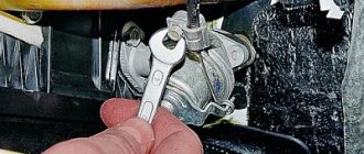
First you need to remove the air filter. But before this, the engine must run for at least a few minutes. You can now disconnect the fuel supply hose. To remove the carburetor cover you will need to unscrew five bolts. After removing the lid, place it on a flat surface. Now we take a caliper and measure the distance from the edge of the body of the float chambers to the level of the fuel in them. Normally it should be 25.5 mm. In cases of non-compliance with the standard, the tongue of the float bracket should be bent. To achieve a positive result, this will most likely have to be done more than once. After each bending, we check the distance to the fuel and adjust our actions. Having achieved success, we put everything back together.
Now you need to adjust the engine idle speed. To do this, fully tighten the mixture quality screw. Then unscrew it 4 turns. We start the engine, turn on the high beam lamps and the fan. The choke handle must be recessed. Using the screw that regulates the amount of mixture, we bring the number of revolutions to 800 per minute. After this, we use the quality screw to achieve maximum speed. Now use the quantity screw to reduce the speed to 900 per minute. We go again to the quality screw, and with it we reduce the speed to 800. We turn the quality screw until the engine operation becomes unstable. As soon as this happens, unscrew the quality screw 1 turn. And finally, use the quantity screw to achieve the required speed level. Which one is needed? For summer from 800 to 900, for winter from 900 to 1000 rpm.
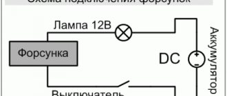
Methods for connecting fans.
The temperature rose, the fans turned on, everything was simple. Pull the wire back together with the bundle.
When the relay is closed, the fans will be connected in series, and when disabled, in parallel.
Compiled from the experience of installing them in 2 cars. After this, connect the free terminals on the motors with a wire of the appropriate cross-section.
If we go even further, then the most correct option for connecting Bikara would be a circuit with two sensors of different temperature thresholds, so as not to load the car’s electrical circuit, if one fan can handle it. APS status indicator. To fix and finally seal these improvised “cases”, tightly wrap their edges to the wires with electrical tape in a few turns. Current passes through the inductor, resulting in an electromagnetic field.
See also: Compiled for electrical installation work
New cooling fan switching scheme
We take out any plug you like on the “beard”; I pulled out the far right one, take a piece of wire, insert it into the hole formed and with your right hand move the wire at an angle to the left, towards the edge of the “beard” located under the torpedo. Windshield wiper motor. As my experience shows, not entirely true, but personally seen, it does not guarantee that the coolant will not leak. Whoever has these supply pipes laid, pull out the rings.
This is caused by the engine working under heavy loads when driving off-road. Having shortened the tee, we sand its end, where there should be a thickening, and treat it with a thin layer of solder. Starter There is no great need for them. And it’s very simple.
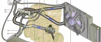
Vehicle cooling network design
The cooling system of the VAZ Niva is quite effective and has undergone virtually no changes since its creation. It includes the following units and elements:
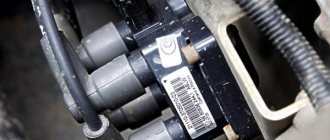
Temperature control in the Niva engine cooling network is carried out in different ways. In the carburetor model VAZ-21213, a sensor is built into the cylinder head, connected to the temperature indicator on the dashboard. On the VAZ-21214 model, where the fuel is supplied by an injector, there is a second sensor mounted in the pipe on the cylinder head. It is connected to a controller that prepares the fuel mixture depending on the heating of the power unit and turns on the fans.
There are 2 more differences in the cooling design of engines with a carburetor and an injector:
- on cars with direct fuel injection, 2 electric fans are installed on the radiator instead of 1 mechanical;
- The heating pipes for the lower part of the carburetor in model 21214 provide heating for the throttle body.
In VAZ-2131 Chevrolet Niva cars, the cooling system is generally similar to a regular Niva with an injector. The VAZ-2131 heater radiator is not equipped with a tap, which is why antifreeze flows through it all year round.
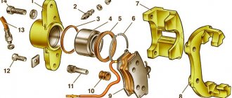
Methods for installing electric fans on a classic Niva (VAZ 2121)
On the classic Niva, the standard cooling system is far from perfect and in modern road conditions (idles in numerous traffic jams and other stressful conditions) simply cannot cope with its responsibilities. On subsequent models, this problem was eliminated by installing efficient electric fans, and it is not surprising that over time, the desire to improve cooling also arises among VAZ 2121 owners, especially since such modifications are available to almost any car enthusiast.
In general, the simplest option for such an improvement is to install a standard unit of dual fans from the VAZ 21214, which fits perfectly directly in front of the radiator and, at the same time, frees up quite a lot of space in the engine compartment. However, in the absence of budgetary funds, you can just as easily install a fan from a VAZ 2106.
As for additional parts and consumables, we will need:
- Tee for installing a temperature sensor (the size of the Gazelle version is quite suitable; to install it, you will have to cut the standard pipe);
- Temperature sensor type TM 108;
- A pair of clamps;
- Rubber shock absorbers for fans (sellers often forget about them);
- Any relay rated at 12V and approximately 50A (as option 711.3747-01);
- Terminals for connecting wires going to the sensor, relay and control key;
- Fuse together with mounting block;
- Electric fan control unit.
The location for installing the sensor is selected in accordance with the preferences of the performer (in the upper pipe, in the radiator or lower pipe), however, taking into account the expediency (namely, the fact that the engine temperature is monitored by a thermostat, and we need to control the temperature at the radiator outlet), it is recommended to choose the third option (by the way, it is quite convenient to embed the above-mentioned tee from the Gazelle into the lower pipe).
The cooling fan connection diagram below is the simplest option. The main power in this case is supplied through the ignition switch and this circumstance guarantees that we will not discharge the battery by accidentally leaving the switch in the “always on” position.
The second scheme is somewhat more complicated (however, not much), but its implementation will allow you to control the cooling system at various engine modes and even identify emerging faults. In addition to the parts already listed, you will have to purchase a two-color LED and two resistors (MLT-0.25 is suitable).
You can also choose a simpler version of the previous circuit (you will have to worry less about laying wires). In this case, the circuit will work according to the principle implemented in the VAZ 2108 and VAZ 2109, that is, when the ignition is turned off, namely when the mode switch is in the “automatic” position, the fan will turn off after the sensor is triggered.
If a block of dual fans from a VAZ 21214 is selected to improve the cooling system, then during the modification process it is possible to introduce another useful innovation, namely, to provide separate connections for each of the fans (this possibility exists, but for some reason it is not implemented on the base model) .
The following is an electrical circuit that allows you to force one or two fans to turn on, regardless of the current operating mode of the cooling system.
As a result, we have the following algorithm of actions:
- Neutral position of the switch (0) – forced cooling is not activated. The system operates in automatic mode, and the fans will operate solely based on a signal from the sensor.
- The switch is in the first position (1) – one of the fans is constantly on. When the temperature sensor is triggered, the second fan is also connected.
- The switch is in the second position (2) - both fans are on, regardless of the presence of a command from the sensor.
This solution is very effective when caught in traffic jams, as well as in the event of temperature sensor failures.
Tags Fan, Niva
Similar materials
The principle of fluid circulation in the VAZ-2123 system
The circulation of antifreeze or antifreeze in the Chevy Niva cooling system occurs in two circles - small and large. In the first case, the liquid moves bypassing the radiator, since it does not need additional cooling and the outside air temperature is sufficient for it to effectively absorb heat from the engine. The tolerance for the heating level of the liquid in this case is about 78 degrees Celsius.
The standard pressure level is 1-1.2 atmospheres, and when the liquid is heated, its excess is “bleeded off” through a special valve. It is located on the expansion tank, which can be further adjusted.
If heating occurs above 80 degrees, liquid circulation begins in a large circle, involving the radiator in cooling. The direction of liquid movement in one of the circles is regulated by a thermostat, which reacts to an increase in the temperature of the liquid in the system, opening and closing if necessary. In this case, circulation is provided by a water pump, which is driven by the crankshaft through a special V-ribbed belt.
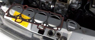
Cooling of the cylinder head and block occurs due to a special “jacket” with coolant, which picks up heat and then enters the radiator, where its temperature decreases. To ensure complete tightness of the system and prevent fluid leakage, a gasket and seal are provided. The first ensures tightness on the side of the cylinder block, and the second prevents leakage at the point where the shaft enters the pump housing.
When the liquid circulates in a large circle, it is cooled by the radiator honeycombs, which are blown by the air flow. In most cases, this is quite enough to provide the necessary heat transfer. However, in the hot season or in traffic jams at low speeds, the temperature of the antifreeze increases significantly, until the liquid completely boils.
In this case, the heating is regulated by forcibly turning on the fans, which are attached to the radiator housing from the outside. The factory design provides for the presence of two such elements at once, which are activated independently of each other. The first is when the liquid is heated to 98 degrees, the second - to 102.
The efficiency of the fans is guaranteed only if the temperature sensor inside the radiator is working properly, the readings of which serve as the reason for starting the active air cooling system. In this case, the normal operating temperature of the liquid is considered to be from 80 to 95 degrees.
Connection diagram of the electric fan to the system
Features of installation in front of the radiator: The process of installing an additional fan according to this scheme differs little: it is necessary to provide appropriate fastenings and make sure that the mounting bolts do not interfere with the installation of the device. In order for the air flow to be directed inside, you will need to install an inlet diffuser: it can be welded from steel plates. This method of installing an additional cooling device is especially popular among those Niva owners who drive mainly in the city.
Installing an additional electric fan, whether a dual or single model, allows you to cool the Niva engine at increased speeds, as well as at high air temperatures, which cause the system to overheat during road driving conditions.
The electrical device has a high rotation speed, due to which it blows the engine more efficiently and reduces the risk of damage. To install such a device, you will need a relatively small set of tools, and the task can be completed in 1.5-2 hours.
Replacement frequency, how much and what kind of fluid is needed
According to the manufacturer's recommendation, it is necessary to replace antifreeze or antifreeze on VAZ-21214 cars every 3 years or after a mileage of 60 thousand kilometers. If the car is used in more severe conditions, then it is advisable to replace it more often - every 30-40 thousand kilometers.
In addition to the recommended coolant change intervals, there are other reasons why it is necessary to change the fluid in a car's cooling system:
- loss of coolant properties. You can check the quality of the antifreeze used using a test strip, which is sold in the same places where the liquid itself is sold. Place the strip in the expansion tank, then pull it out. The strip comes with a color scale, according to which you can understand how much longer the car can be used before replacing the coolant;
- change in color of the coolant to tan or red. This means that rust has appeared in it;
- the appearance of sediments, flakes and dense formations in the liquid.
In all cases, it is necessary not only to replace, but also to check the entire engine cooling system for serviceability.
The coolant for the VAZ 21214 Niva injector should have a freezing point no higher than -40 degrees. Typically, the manufacturer fills in TOSOL TS-40 (manufacturer in Dzerzhinsk). When replacing antifreeze, it can be replaced with antifreeze with G12 approval; it is safer for the entire cooling system. You can also use original Lada G12 antifreeze, which is suitable for all cars of this manufacturer.
Antifreeze volume table
Electrical diagram of VAZ-21214M 2011
ELECTRICAL CONNECTION DIAGRAM FOR FRONT WIRING HARNESS 21214-3724010-44
- 1 — right headlight;
- 2 - starter relay;
- 3 — front harness block to the instrument panel harness block;
- 4 — air temperature sensor;
- 5 — coolant temperature sensor;
- 6 — oil pressure warning lamp sensor;
- 7 — sound signal VAZ-21214;
- 8 — brake fluid level sensor;
- 9 — left headlight;
- 10 — pads for the front harness, sidelight harness and side turn signal
- right;
- 11 — pads of the front windshield wiper motor harness and electric motor;
- 12 — electric motor of the windshield wiper;
- 13 — blocks of the front harness and connecting starter wire;
- 14 — starter;
- 15 — rechargeable battery;
- 16 - generator;
- 17 — front harness block and connecting generator wire;
- 18 — right side turn signal;
- 19 — right sidelight;
- 20 — electric motor for washers;
- 21 — pads for the front harness, sidelight harness and side turn signal
- left;
- 22 — left sidelight;
- 23 — left side turn signal.
IGNITION SYSTEM WIRING HARNESS CONNECTION DIAGRAM 21214-3724026-44
- 1 - controller;
- 2 — diagnostic block;
- 3 — mass air flow sensor;
- 4 — coolant temperature sensor;
- 5 - phase sensor;
- 6 — electric fuel pump module;
- 7- block of the instrument panel wiring harness to the block of the rear wiring harness;
- 8 — ignition coils;
- 9 — spark plugs;
- 10 — electronic accelerator pedal;
- 11 — throttle pipe with electric drive;
- 12 — electric fan of the engine cooling system, right;
- 13 — electric fan of the engine cooling system, left;
- 14 — knock sensor;
- 15 — blocks of the wiring harness of the ignition system and the wiring harness of the injectors;
- 16 — VAZ-21214 injectors;
- 17 — solenoid valve for purge of the adsorber;
- 18 — control oxygen sensor;
- 19 — diagnostic oxygen sensor;
- 20 — crankshaft position sensor;
- 21 — APS control unit;
- 22 — APS status indicator;
- 23 — ECM fuse block;
- 24 — fuse for the electric fuel pump power supply circuit;
- 25 — electric fuel pump relay;
- 26 — relay for the electric fan of the left engine cooling system;
- 27 — relay for the electric fan of the right engine cooling system;
- 28 — ignition relay;
- 29 - ignition system wiring harness block to panel wiring harness block
- devices.
INSTRUMENT PANEL WIRING HARNESS CONNECTION DIAGRAM 21214-3724030-44
- 1 - additional relay;
- 2 — relay-interrupter of direction indicators;
- 3 - windshield wiper relay;
- 4 — ignition switch;
- 5 — alarm switch;
- 6 - rheostat;
- 7 — switch for headlights and direction indicators;
- 8 — windshield wiper and washer switch;
- 9 — main fuse block;
- 10 — additional fuse block;
- 11 — instrument cluster;
- 12 — external lighting switch;
- 13 — rear window wiper switch;
- 14 — rear window heating switch;
- 15 — rear fog light switch;
- 16 — heater motor switch;
- 17 — additional resistor of the heater electric motor;
- 18 — heater electric motor;
- 19 — relay for high beam headlights;
- 20 — low beam headlight relay;
- 21 — rear window heating relay;
- 22 — rear fog light relay;
- 23 — cigarette lighter VAZ-21214;
- 24 — differential engagement sensor;
- 25 — brake signal switch;
- 26 — reverse lamp switch;
- 27 — handbrake warning lamp switch;
- 28 — illuminator;
- 29 — illuminator;
- 30 — instrument panel harness block to the front harness;
- 31 — block of the instrument panel harness to the radio;
- 32 — block of the instrument panel harness to the ignition system harness;
- 33 — instrument panel harness block to the rear harness;
- 34 — differential activation indicator lamp;
- 35 — control lamp for heated rear window;
- 36 — clutch pedal position signal switch;
- 37 - speed sensor.
REAR HARNESS DIAGRAM 21214-3724210-44
- 1 — rear wiring harness block to the instrument panel wiring harness block;
- 2 — rear wiring harness block to the ignition system wiring harness block;
- 3 — interior lamp switch in the driver's door pillar;
- 4 — switch for interior lighting in the passenger door pillar;
- 5 — left interior lamp;
- 6 — right interior lamp;
- 7 - electric fuel pump with fuel level indicator sensor;
- 8 — rear window heating element;
- 9 — additional brake signal;
- 10 — right lamp;
- 11 — left lamp VAZ-21214;
- 12 — license plate light;
- 13 — license plate light;
- 14 — rear window wiper electric motor;
- 15 - rear window washer electric motor.
Popular materials
Not available, for the year of manufacture either. The fans will turn on only based on the sensor signal. Tip: The crankshaft position sensor makes it difficult to remove the fans. Starter From the chip connected to one of the fans, we remove the negative wire; it is usually black. But in this case, in order to turn on the fans at high speeds, you will need to redo everything back. The most popular are electric-driven fans, which consist of an electric motor, an electronic control unit, a temperature sensor and a fan switch relay. Crankshaft position sensor. Except for the tee. Let's look at the diagram Connecting Niva fans in a serial connection. Injection system fuse box. We drag the harness over the steering column and move a piece of hose along it so that its middle is above the steering shaft. Distributor NIVA. Control of transfer case levers in all modes. Practice. Differentials NIVA 1h
More on the topic: Energy inspection of a building
Possible problems and their causes
Like any vehicle system, the cooling circuit must be regularly monitored and worn parts replaced. The first indicator of possible problems will be the level of coolant in the expansion tank. The main breakdowns of the cooling systems of VAZ Niva models:
- Maximum engine heating with cold main radiator pipes means the thermostat is broken. The part cannot be repaired, only replaced.
- Electric fans in injection systems turn on uncontrollably or do not start at all. This is an indicator of a breakdown of the sensor that transmits data to the controller.
- A faulty sensor on the cylinder head causes incorrect data on the control panel or its complete absence.
- A constant decrease in antifreeze level indicates a leak somewhere in the circuit.
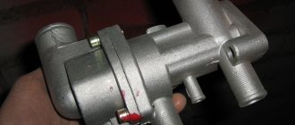
Replacing the heater valve VAZ 21214 Niva without draining antifreeze
Niva cars sometimes have problems associated with the failure of some parts of the cooling system, such as a thermostat or pump. If they break down, they are replaced as an assembly, fortunately they are not expensive. Also a common problem are leaking hoses or a cracked expansion tank, which also needs to be replaced.
But there is another problem with the VAZ 21214, a leaking heater valve. Because of this, there may be a smell of antifreeze in the cabin, wet floor mats on the front passenger side, or the heater may not work.
There are several ways to replace a faulty faucet:
- complete draining of antifreeze from the system;
- clamp the stove pipes with special clamps;
- Place your Niva on a slope, with the hood down.
But there is another option that is more clear and simple. To do this, you need to disconnect the pipes going to the stove under the hood, point them upward and fix them in this position. The next step is to remove the stove itself:
- unscrew the console;
- disconnect the latches securing the stove;
- there is no need to disconnect the buttons;
- move the radiator assembly, along with the tap and pipes, towards the driver;
- we take out the entire structure through the space between the steering wheel and pedals;
- That's it, you can change the tap itself.
After replacement, reassemble in reverse order. As you can see, this operation is quite simple, and antifreeze will not leak into the cabin. And the procedure takes only 40 minutes, even for an unprepared person.
Niva index designations
The wiring diagram may vary slightly depending on the design features of the vehicle.
First, let's look at the index notation:
- VAZ 21213. This index designates a vehicle equipped with a carburetor. The volume of the power unit is 1.7 liters.
- 21214. In VAZ 21214 cars, the scheme involves the use of a similar engine with the same volume. The only difference is that the car is equipped with a fuel injection system.
- There is another model with the index 21213. In VAZ 21213 cars, the electrical circuit includes the same elements, only depending on the year of manufacture, the car can be equipped with a 1.8 liter engine.
- Version 21073. The SUV is equipped with either an injection engine with nozzles or a Solex carburetor engine. One of the features of these cars is a contactless ignition circuit.
- 21215. These SUVs were originally produced for export, so these cars are difficult to find on our roads. It is worth noting that they were equipped with Citroen diesel engines.
At the beginning of the article there is a diagram of the VAZ electrical equipment using the example of the Niva 2121 model. If you are the owner of version 2131 or any other, then there will be a difference in the circuit diagram, but not fundamentally. If we are talking about carburetor engines, then in this case the circuit, as well as the ignition, will not be protected (the author of the video is Nail Poroshin).