09.29.2021 15 105 VAZ 2107
Author: Ivan Baranov
As with any car, the generator on the VAZ 2107 injector works in parallel with the battery - these are two power sources for the car, which are used in different modes. The article discusses the generator 37.3701, the principle of operation of the generator with different characteristics, including a maximum current of 80 Amperes, and provides instructions for connecting the unit. The G222 generator set is similar, you just need to pay attention to some differences.
[Hide]
Generator VAZ 2107: purpose and main functions
As with any other car, the generator on the “seven” works in tandem with a battery. That is, these are two power sources in the car, each of which is used in its own modes. And if the main task of the battery is to maintain the functionality of electronic devices during the period when the engine is turned off, then the generator, on the contrary, produces current only when the engine is running.
The main task of the generator set is to generate electrical energy by charging the battery. That is, in many ways (if not all) the performance of the machine depends on how well the generator and battery work.
Generator sets for the VAZ 2107 have been produced since 1982. Their factory marking is G-221A.
All VAZ classic cars, including model 2107, were equipped with G-221A generators
Technical characteristics of the generator G-221A
The VAZ 2107 was equipped with two types of generators (carburetor and injection), each of which had its own factory marking: 372.3701 or 9412.3701. Therefore, the operating characteristics of the devices may differ, since injection models consume more electricity, and accordingly, the generator power must be higher.
All VAZ 2107 generators have the same rated voltage - 14 V.
The generator for a carburetor car has modification 372.3701 and is made in an aluminum cast housing with steel fasteners
Table: comparison of characteristics of different modifications of generators for VAZ 2107
| Generator name | Maximum output current, A | Power, W | Weight, kg |
| VAZ 2107 carburetor | 55 | 770 | 4,4 |
| VAZ 2107 injector | 80 | 1120 | 4,9 |
Types of breakdowns
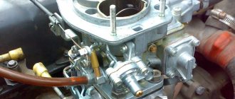
Generator VAZ 2107
What malfunctions occur if the generator does not work correctly?
- Extraneous noise appears.
- Complete lack of battery charging while the engine is running.
- Overheating and failure of the same battery.
- Damage to any or all energy consumers, including the injector.
- Increased or decreased voltage in the electrical system. The standard voltage is 13.6-14.5 V.
- Mechanical or electrical damage to the elements of the generator itself.
Obviously, this node requires special attention.
What generators can be installed on the “seven”
The design of the VAZ 2107 allows the installation of not only the G-221A generator. Therefore, if necessary, the driver can install a more powerful device, however, this will require making some changes to the electrical circuit of the car. The question arises: what is the reason for the desire of a car enthusiast to change his “native” generator?
The G-221A was the optimal device for equipping cars at the beginning of their mass production. However, a lot of time has passed since the 1980s and today almost every driver uses modern electronic devices:
- acoustic system;
- navigators;
- additional lighting devices (tuning), etc.
Non-standard lighting devices consume the most electricity
Accordingly, the G-221A generator cannot cope with high loads, which is why drivers begin to look for more powerful units.
You can install at least three more powerful devices on the “seven”:
- G-222 (generator from Lada Niva);
- G-2108 (generator from the G8);
- G-2107–3701010 (injection model for a carburetor car).
It is important that the last two models do not require changes in the design of either the generator housing or its mountings. When installing a generator from Niva, you will have to make some modifications.
Video: principle of operation of the generator
Connection diagram G-221A
Being an electronic device, the generator needs to be used correctly. Therefore, its connection diagram should not cause ambiguity. It should be noted that drivers of “sevens” can usually easily connect all the generator terminals themselves, since the circuit is accessible and understandable to everyone.
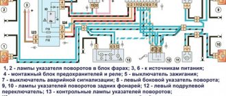
The generator (item 2) is connected to the circuit in series between the battery (item 1) and the mounting block (item 3)
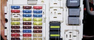
Many car owners wonder where which wire should be connected when replacing the generator. The fact is that the device has several connectors and wires, and when replacing, you can easily forget which wire goes where:
- orange is not useful for connection, it can be left as is or connected to gray directly to autostart the car;
- a gray thick wire goes to the brushes from the relay regulator;
- a gray thin wire connects to the relay;
- yellow - coordinator of the control light on the control panel.
When working independently with the G-221A, it is better to sign the purpose of the wires so as not to connect them by mistake later.
To avoid errors, all wires have their own color designation
Principle of operation
The principle of operation is this: you turn the key in the lock, and current flows to the excitation wire. The magnetic field that the armature creates penetrates the stator windings, at the terminals of which voltage appears. When the armature reaches a sufficiently high rotation speed, which is provided by the pulley and belt drive, the so-called self-excitation mode occurs.
The rectifier unit converts alternating current into direct current. The voltage regulator starts working when the crankshaft speed changes (accordingly, the armature rotates faster or slower) and regulates the time for which the field wire is turned on. Sometimes a generator malfunction may occur due to a blown fuse in the circuit.
The device of the VAZ 2107 generator
Structurally, the generator on the “seven” has the shape of a cylinder. The cast body contains many small parts, each of which performs its own functions. The main elements of the G-221A are the rotor, stator and covers, which are cast only from a special aluminum alloy.
Rotor
The G-221A rotor consists of a shaft with a corrugated surface, onto which a steel sleeve and poles are pressed. The bushing and beak-shaped poles together form the so-called core of the electromagnet. The core produces an electromagnetic field during the rotation of the rotor shaft.
The excitation winding is also located inside the rotor. It is placed between the poles.
The moving element of the rotor - the grooved shaft - rotates thanks to two ball bearings . The rear bearing is mounted directly on the shaft, and the front bearing is fixed on the generator cover.
The rotor is pressed into the generator winding and does not separate from it during disassembly
Stator
The stator is assembled from special plates 1 mm thick. The plates are made of electrical steel. It is in the stator slots that the three-phase winding is located. The winding coils (there are six in total) are made of copper wire. Strictly speaking, the electromagnetic field coming from the rotor core is converted by the coils into pure electricity.
Wire breaks or carbon deposits on its surface can affect current generation
Rectifier
The generator in the described configuration produces only alternating current, which is clearly not enough for the smooth operation of the car. Therefore, in the G-221A case there is a rectifier (or diode bridge), the main task of which is to convert alternating current into direct current.
The diode bridge has the shape of a horseshoe (for which it received the corresponding nickname among car enthusiasts) and is assembled from six silicon diodes. On the plate, three diodes have a positive charge and three have a negative charge. A contact bolt is installed in the center of the rectifier.
Structurally, the rectifier really looks like a horse's horseshoe
Voltage regulator
The voltage regulator on the VAZ 2107 is made together with a brush holder. The device is a non-separable unit and is fixed to the back cover of the generator. The regulator is designed to maintain the rated voltage in the network in any operating mode of the engine.
The regulator's electrical circuit controls the voltage in the device
Pulley
The pulley is not always considered an integral part of the generator, since it is mounted separately on an already assembled housing. The main task of a pulley is to transmit mechanical energy. As part of the generator, it is connected by a belt drive to the crankshaft and pump pulleys. Therefore, all three devices work in an inextricable connection with each other.
The pulley is mounted on the rotor shaft and connected by a belt drive to the corresponding parts of the pump and crankshaft
Malfunctions and their elimination
Let's start with the simplest and most obvious. From the work of indicators. These are the difficulties that may arise.
Constantly lit indicator (even when the ignition is turned off)
To eliminate the problem, you will need to replace the diode bridge with a new one. The reason for this was a short circuit on it. You can try to repair it, but this requires knowledge. Replacement cost is low.
Devices and sensors do not work
To do this, you will need to check all wiring and contacts. Often the cause of such an incident is the fuse box. It is necessary to check the voltage in all areas to determine the location of the fault. If the cause is the generator, then you need to check the belt tension and the stability of the pulley. Next, the “chocolate”, brushes, and diode bridge must be checked.
The battery indicator is always on when the ignition is on
You need to start by checking the battery. In this case, the inspection is carried out both on a cooled down car and on a warm one. If overheating and boiling occurs, then you need to check the voltage regulator unit on the generator and check the wear of the brushes. We must not forget about the belt, pulley and bearings. To avoid unnecessary work, you need to measure the voltage between the generator and the battery. Most often this is a signal that the battery is not charging.
The indicator flashes
If in the previous case there is often not enough charging, here, on the contrary, there is a recharge. The regulator and brush assembly need to be replaced.
Noise
The noise may be caused by worn bearings, excessive tension or loosening of the belt. You need to make sure that all fasteners are secure and the gaskets are intact. Less commonly, the cause of this is a malfunction of the rotor or stator. And, again, the same generator brushes can make the most unpleasant sounds. In this case, they are changed or wiped with gasoline.
Voltage drops
This is best seen at night. If the headlights burn unevenly and constantly change light intensity, then the voltage regulator needs to be replaced.
Generator faults
Unfortunately, mechanisms have not yet been invented that would not fail under the influence of time and constant loads. The VAZ 2107 generator is designed for many years of operation, but in some cases this is hampered by minor breakdowns and malfunctions of its components.
You can identify problems with the generator without the help of service station specialists: you just need to carefully monitor all the changes that occur with the car while driving.
The charging indicator light on the instrument panel came on
In the interior of the VAZ 2107, there is a terminal for several signaling devices on the dashboard. One of them is the battery charging indicator light. If it suddenly lights up red, it means there is not enough charge in the battery or there is a problem with the generator. But the alarm does not always indicate a problem with the generator itself; most often the lamp goes off for other reasons:
- slipping of the generator belt drive - you will need to stop the machine and adjust the degree of belt tension;
- there is damage in the warning lamp relay, so it does not work correctly - it is recommended to “ring” the relay in the mounting block and, if necessary, replace it;
- breakage of contacts in the excitation winding is a more serious damage that requires removing the generator from the car, disassembling it and searching for a break;
- severe wear of the brushes in the brush holder - they will need to be replaced, which is quite simple;
- short circuit in the rectifier (most likely, one of the silicon diodes has burned out) - it is recommended to disassemble the generator, test the diodes and replace the failed element.
The driver will immediately notice the signal, as the lamp begins to glow bright red on the instrument panel
The battery is not charging
VAZ 2107 drivers often encounter this problem: the generator seems to be working properly, but there is no power to the battery. The problem may lie in the following malfunctions:
- the alternator belt has stretched - you need to check the degree of its tension or replace it with a new one;
- loosening the fastening of the wire tips - just tighten all the fastening connections and thoroughly clean the contacts and connectors;
- malfunction of the battery itself;
- Damage in the wiring - it is recommended to ring all the wires between the battery and the generator and replace the damaged areas.
If there is no charging, the problem may lie in both the generator and the battery.
The battery is boiling over
Battery boiling over is a sign that the battery does not have long life left. After this, the battery will not be able to function fully, so it will have to be replaced soon. However, so that the replacement does not lead to the same sad consequences, it is necessary to find the cause of the boiling, which may be:
- contamination of the contact between the ground and the housing of the generator regulator - cleaning of the contact is necessary;
- damage to the voltage regulator board itself - replacement of the board is recommended;
- defective battery - if the battery began to boil away immediately after replacement.
It is better not to use the battery after boiling, as its resource is very limited.
When driving there is noise and grinding noise from the generator
The generator has a rotating rotor, so it must make noise during operation. However, if these sounds become increasingly loud and unnatural, you should understand the cause of their occurrence:
- loosening the nut on the pulley - you need to tighten the nut and check the degree of belt tension;
- deterioration of the bearings - in this case, the driver may hear a loud grinding noise and even a howl while driving; it will be necessary to press out the old bearings from the shaft and install new ones;
- short circuit in the winding - the entire stator needs to be replaced;
- creaking brushes - it is recommended to clean the brushes from adhering dirt.
What should you pay attention to?
To carry out repairs, you need to have a general understanding of electricity and its properties. If with mechanical breakdowns everything is much simpler and often a visual inspection is enough to detect a part that needs replacement, then with electrical faults there is no such clear visualization. Moreover, the initial cause of generator breakdowns may be a malfunction of another component of the VAZ 21074, for example, the same battery. And vice versa. Very often a chain reaction is detected, with damage to several nodes.
In such cases, it is important to discover the cause before taking action. Otherwise, there is no guarantee that after replacing one or another element everything will not happen again.
As mentioned earlier, you cannot check the operation of the generator on the VAZ 21074 using the old method of tilting the terminals. Don't forget about the injector and ECU.
It is better not to buy a used generator, but to buy a new one. But even in this case, you need to check the voltmeter readings and battery charging more often than usual. Alas, even new factory products are sometimes defective. Therefore, it is better to play it safe, thereby protecting all electronics, injector, battery and other devices from overvoltage. This is really important.
If you don’t have confidence in your abilities, then it’s better to immediately contact a workshop. And one more important detail. If any element installed in the generator fails, service centers first of all offer its complete replacement rather than partial replacement. Of course, this approach has its advantages, but when the warranty period has expired, it is very expensive.
The housing of the voltage regulator unit becomes very hot during operation. You need to keep the wires away from it.
To regularly monitor fluctuations in voltage and battery charge level, you can purchase an on-board computer that includes a similar function. In addition, this will be useful for many other components of the VAZ 21074. Such a device is indispensable on cars where an injector is installed.
Generator check
Problems with the generator set can be avoided if the condition of this unit is periodically diagnosed. Checking the functionality of the generator gives the driver confidence that it is working properly and there is no cause for concern.
You cannot test the generator by disconnecting it from the battery while the engine is running. This is fraught with power surges and short circuits . The easiest way is to contact a service station specialist to check the functionality of the generator on a stand. However, convinced “seven guides” have long adapted to checking the G-221A on their own using a multimeter.
For diagnostics, you will need a multimeter of any type - digital or indicator. The only condition: the device must work correctly in both AC and DC measurement modes.
Operating procedure
Two people will be required to diagnose the generator's functionality. One of them should be in the cabin and, upon a signal, start the engine, the second should directly monitor the multimeter readings in different modes. The operating procedure will be as follows.
- Switch the device to constant current mode.
- With the engine turned off, connect the multimeter first to one terminal of the battery, then to the second. The network voltage should not be less than 11.9 and more than 12.6 V.
- After the initial measurement, start the engine.
- When starting the engine, the measurer must carefully monitor the instrument readings. If the voltage drops sharply and does not rise to operating condition, this indicates the exhaustion of the generator's life. If, on the contrary, the voltage indicator is higher than normal, then the battery will soon boil away. The best option is that when you start the engine, the voltage drops slightly and immediately recovers.
If the voltage measured with the engine running is between 11.9 and 12.6 V, then the generator is ok
Video: procedure for checking a generator with a light bulb
Device components
If the generator device is considered in terms of size, then there are compact and traditional ones. They also differ in their design features.
- drive pulley;
- excitation wire;
- bracket;
- anchor device.
They can be fastened with one bolt, or with several, and other “little things”. However, any generator has a general structure.
- The rotor (or armature) is the rotating part of the generator. The armature is designed to create a magnetic field using an excitation winding located on the shaft. The excitation wire is powered by slip rings located on the same shaft. The following are also located here: the excitation winding wire, the fan impellers (one or two), the drive pulley and the bearing assembly;
- The stator is the stationary part of the generator, consisting of three windings (three-phase), which create alternating current. These windings can be connected to each other by the so-called “star” or “delta”;
- The housing is most often made of lightweight non-magnetic aluminum alloy; it consists of two covers, secured with a bolt. The front cover is located in the same place as the drive pulley; the back cover is on the side where the slip rings are. Each bolt that connects the back and front covers is tightened. In the future, to disassemble the generator on a VAZ 2110, it is enough to remove the bolt mounts;
- Mounting the generator on a VAZ 2110. There is an upper mounting bracket that uses 2 bolts. The lower mounting bracket most often has one bolt, but there may be two, in which case minor modifications may be necessary. The bolt can be anything, the main thing is that the size is suitable, sometimes a sleeve is required for this. It is better not to redo the bracket itself. The bracket securely holds the generator, which has many responsibilities. And yet, we should not forget that the bracket, like the bolt, can break, so you need to monitor its condition;
- The structure of the brush assembly consists of two graphite brushes, springs that press them, and a brush holder;
- In modern Katek generators, the voltage wire and brush holder are located together in a non-separable unit. Therefore, if the voltage regulator fails, the entire assembly must be replaced. Structurally, this regulator can have a hybrid device - when radio elements with electronic devices are in the same circuit. But an integral is when the regulator is made in thin-film microelectronics technology. Many believe that the integral regulator copes better with its mission - controlling the duration and frequency of current pulses. The regulator changes the voltage used to charge the battery. At higher temperatures, less voltage goes to the battery. Although, in principle, it is not so important whether the integral is responsible for this regulation, or the hybrid;
- A rectifier unit with six diodes is responsible for converting the alternating current generated by the armature and stator into direct current, directly used by all on-board equipment. It also serves to charge the battery;
- The device is driven by a belt drive. It provides a significant increase in the speed at which the crankshaft rotates. In this case, the V-belt wears out faster if the pulley has a small diameter. If the driven pulley is small, it is better suited to a serpentine drive, which is more often used in modern generators.
Generator set belt for VAZ 2107
The VAZ 2107 car was produced from 1982 to 2012. Initially, the model was equipped with a smooth drive belt (old model). Over time, the “seven” was modified several times and at the end of the 1990s, the generator began to work with a new type of belt with teeth.
The most popular among car owners are rubber products from the German company. These belts fit perfectly into the operation of a domestic car and serve for the entire period specified by the manufacturer.
The operation of the generator and the entire vehicle depends on the quality of the drive belt.
The design numbers and sizes of the belts are indicated in the vehicle’s service book:
- 2101–1308020 (smooth surface), dimensions - 10.0x8.0x944.0 mm;
- 2107–1308020 (toothed surface), dimensions - 10.7x8.0x944.0 mm.
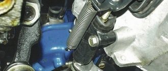
How to tension a belt on a generator
The operation of the generator, as well as the water pump, primarily depends on the correct tension of the belt on the pulley. Therefore, existing rules cannot be neglected. The belt is installed and tensioned in the following order.
- Place the assembled generator in place, lightly tightening the fixing nuts.
- Take a pry bar and use it to fix the gap between the generator housing and the pump.
- Place the belt on the pulley.
- Without releasing pressure from the pry bar, pull the belt onto the pulley.
- Tighten the top nut securing the generator until it stops.
- Check the degree of belt tension - the rubber should not sag, but it should not be too tight.
- Tighten the lower nut securing the generator.
A well-tensioned drive belt should give slight deflection when pressed, but not be excessively loose.
Video: how to tighten the alternator belt
Checking the degree of tension is done with two fingers. You need to press the free part of the belt and measure its deflection. The optimal deflection is 1–1.5 centimeters.
Thus, we can say that independent maintenance of the generator on a VAZ 2107 is quite possible and does not fall into the category of impossible tasks. It is important to follow the recommendations and algorithms for this or that work in order to carry out quality repairs or diagnostics. However, if you have doubts about your skills and abilities, you can always turn to professionals for help.
Self-diagnosis
So we smoothly approached the issue of verification. If you don’t know how to check the functionality of a unit in your car, then first of all carry out a visual diagnosis of the device’s condition. If the check shows that there is no external damage, then a more thorough diagnosis is needed. Initially, you should check the winding for insulation damage; you will need a multimeter or a test lamp to check.
Before checking, one wire from the lamp must be connected to the armature shaft, and the other wires must be touched in turn to the collector plates. Please note that when checking, the wire tips must be reliably insulated. In the event that the armature winding shorts to ground, the light should blink.
To check the turn-to-turn short circuit you will need a special induction device. The core of the device in this case is made of metal, and the coil is powered using industrial alternating voltage. The armature is installed in the prism of the core, after which it must be rotated around its axis, and an iron plate must be connected to the metal. In the absence of short circuits, there will be no current in the winding (the author of the video is the Ramanych channel).
If there is a short circuit, then an electromotive force will be recorded in the closed turns. In this case, the alternating voltage will contribute to the formation of another magnetic field, so if there is one, then vibration will appear in the iron plates connected to the armature. The presence of vibration may indicate that there is a short circuit in the turns; if this is the case, then the only option to solve the problem is to rewind the armature.
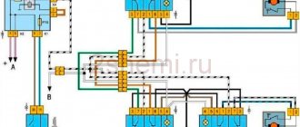
Charging diagram for VAZ with injection engines
This scheme is identical to the schemes on other VAZ models. It differs from the previous ones in the method of exciting and monitoring the serviceability of the generator. It can be carried out using a special control lamp and a voltmeter on the instrument panel. Also, through the charge lamp, the generator is initially excited at the moment it starts working. During operation, the generator operates “anonymously,” that is, excitation comes directly from pin 30. When the ignition is turned on, power through fuse No. 10 goes to the charging lamp in the instrument panel. Then it goes through the mounting block to pin 61. Three additional diodes provide power to the voltage regulator, which in turn transmits it to the excitation winding of the generator. In this case, the indicator lamp will light up. It is at that moment when the generator operates on the plates of the rectifier bridge that the voltage will be much higher than that of the battery. In this case, the control lamp will not light up, because the voltage on its side on the additional diodes will be lower than on the side of the stator winding and the diodes will close. If the control lamp lights up while the generator is running, this may mean that additional diodes are broken.
Principle of operation
In order for the generator to supply current to the load, the field winding must be energized. This, in fact, happens when we turn on the ignition. Next, the crankshaft of a running engine causes the armature to rotate. At this time, electricity begins to be generated in the stator winding, which is sent to the on-board network.
In VAZ-2110 cars, the generator produces alternating current, and all consumers are designed for direct current. To convert it, a rectifying diode unit is used.
But that's not all. The fact is that the voltage produced by the generator constantly changes depending on the number of crankshaft revolutions. To stabilize it, a voltage regulator relay is used.
As a result, at the terminals of the device we have a constant electric current of stable voltage.
Monitoring the performance of components
To perform this operation, it is necessary to remove the device from the vehicle and clean it of dirt. The verification procedure is as follows:
- We switch the multimeter to resistance measurement mode. We install the positive probe on terminal “30”, and the negative probe on ground. Readings close to zero indicate that the bridge or generator stator has failed.
- Positive diodes are checked by installing a positive probe on the terminal of one of the rectifier unit mounting bolts, and a negative probe on ground. Zero or close to zero instrument readings indicate that the diode bridge is faulty.
- To check the rotor, it is necessary to measure the resistance between the slip rings. In working condition it should be within a few ohms. If the resistance is near zero, then a short circuit has occurred in the winding.
The diode bridge and other faulty elements of the generator must be replaced with new ones from spare parts.
DIY Generator Connection Guide
with an injector or carburetor can become:
- burnt windings;
- an interturn short circuit has occurred;
- mechanical damage to the housing;
- malfunction of a three-level regulator, etc.
The generator replacement procedure consists of removal, installation and connection.
- First of all, we de-energize the car by removing the negative terminal from the battery.
- Disconnect the connector from the generator set.
- Having removed the protective cover, you need to disconnect the terminal with a “10” key and remove the wire.
- After loosening the generator, you need to remove the drive belt.
- Using a “17” wrench, unscrew the nuts and remove the adjusting bar.
- After unscrewing the lower fastening nut, remove the bolt and bushing.
- We dismantle the generator.
Unit removed for repair
The generator set is installed in the reverse order. Before installing the unit, you need to thoroughly study the connection diagram of the 2107 generator with an injector or carburetor, as well as the electrical connection diagram
In this case, you need to pay attention to the difference between 37.3701 and G222
After installation, you need to adjust the belt tension. To adjust the belt tension, you need to loosen the two bolts securing the unit. Using a pry bar, tighten the belt and secure it in this position with a nut on the adjusting plate. Then you need to check the degree of tension. To do this, you need to press the belt in the gap between the pulleys.
The deflection should be in the front from 10 to 17 mm. The procedure should be repeated until the desired value is achieved. After tensioning, all fastening nuts are finally tightened. At this point, the connection of the unit can be considered complete.
Generator repair
The VAZ 2107 generator is a rather complex unit, the repair of which involves partial or complete disassembly, but first the device must be removed from the car. To work you will need the following tools:
Dismantling the generator
We carry out work on removing the generator in the following order:
Video: dismantling the generator on a “classic”
Disassembly
To disassemble the unit you need the following tools:
The disassembly sequence is as follows:
If the diode bridge needs to be replaced, then we perform the described sequence of actions, after which we install a new part and reassemble the unit in the reverse order.
Generator bearings
Before you start replacing generator bearings, you need to know what their dimensions are and whether it is possible to install analogues. In addition, it is worth considering that such bearings can be structurally open, closed on one side with a steel washer and closed on both sides with rubber seals, which prevent dust from entering and lubricant leakage.
Table: dimensions and analogues of generator bearings
| Applicability | Bearing number | Analogue import/China | Dimensions, mm | Quantity |
| Rear generator bearing | 180201 | 6201–2RS | 12x32x10 | 1 |
| Front generator bearing | 180302 | 6302–2RS | 15x42x13 | 1 |
Replacing bearings
Replacing the bearings on the “seven” generator is carried out on a disassembled device using a special puller and a key 8. The procedure is performed as follows:
Regardless of which bearings I change on my car, I always open the protective washer and add grease before installing a new part. I explain such actions by the fact that not every manufacturer is conscientious about filling bearings with lubricant. There have been cases where the lubricant was practically absent. Naturally, such a part would simply fail in the near future. I use Litol-24 as lubricants for generator bearings.
Voltage regulator
A relay regulator, like any other device, can fail at the most inopportune moment. Therefore, it is important to know not only how to replace it, but also what options there are for this product.