Let us remind you that the emergency signaling is carried out by the same electrical circuit that turns on the direction indicators. Therefore, it is possible that problems in the electrical circuit will be similar. But before we start talking about malfunctions, let’s remember what the electrical circuit of the alarm on the VAZ 2114 looks like and how it turns on. Also from the same article, the reader will learn how to move the emergency button from under the steering wheel to the dashboard and install an elegant Euro button.
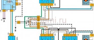
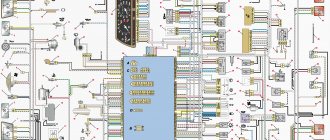
Emergency gang diagram for VAZ 2114
Electric current from the power source (3) enters the mounting block (4), where it passes through two fuses and a relay to buses 2 and 4 through the X11 chip of the mounting block. From the mounting block, the wires go to the ignition switch and hazard warning switch, which has several modes. There is another turn signal switch in the electrical circuit, which is called the left steering column switch (12). The turn signal headlights in the diagram are indicated by numbers:
- 1,2 – front,
- 8, 11 – side,
- 9.10 – rear.
Useful: Where
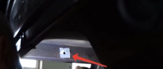
To complete the picture, we provide, as an illustration, a diagram of the location of fuses and relays in the mounting block.
Windscreen wipers
As for the windshield wipers of the Lada Priora, the electrical circuit in this case has a special programmable control unit. The circuit contains fuses to protect against overvoltages and short circuits.
The windshield wipers are turned on with a switch located near the steering wheel. The switch has eight positions, four of which are used to control the purifier. One position on the switch turns on the glass washer, the other two positions control the rear wiper. Another position is responsible for the disabled state of the windshield wiper.
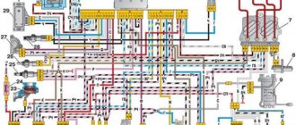
Connection diagram for Euro button on VAZ 2114
The figure shows a diagram of connecting turn signals and emergency lights with a new Euro button.
The location of the original emergency button caused a lot of complaints from car owners.
The AvtoVAZ emergency flasher has another significant drawback - its tendency to stick. That is, you turn it on, but how to turn it off is a problem. You have to arm yourself with tools, remove the button from under the steering wheel and fix the loose fastener. This is what causes the sticking.
Useful : The emergency lights and turn signals on the VAZ 2114 do not work
Fortunately, the same engineers provided one slot for a button on the dashboard. Obviously, they left this slot for installing additional equipment in case the car owner wants to modernize the interior, or do tuning in it, and add some cutting-edge device. For now, this nest is closed with a plug (pseudo-button). Almost all car owners bring their emergency lights here, since pressing on them here is much more convenient than somewhere under the steering wheel.
At the beginning of the section there is a diagram of the VAZ 2114 emergency gang, according to which the Euro button will be redone. First, at the nearest car market or in an online store that sells spare parts, we find the Euro button.
You will also need a four-pin relay with a connector (with a block). First, the old button must be dismantled and the wires removed from it. We won't need it anymore. And the wires with contacts will still serve. For ease of connection, the wires can be labeled. Below is a diagram for connecting an emergency light on a VAZ 2114. The diagram shows how to move the wires from the old button to the new one and connect a four-pin relay.
In accordance with the diagram of the emergency signal button on the VAZ 2114, the wires are transferred to the new button and connected to a four-pin relay.
You will get a kind of garland of wiring and devices. This garland is to be mounted in the dashboard of the car. The chip from the old button is removed and the ends of the garland are inserted into its connectors.
If everything was done correctly, the button will work. Now you have to insert the button in place of the plug and remove the wires under the dashboard. By the way, the minus is taken from the minus of the on-board computer. To insert the emergency signal chip into its place, the wires will have to be disconnected for a while. The wiring harness runs from the steering column under the on-board computer. To do this, you will have to remove the corresponding casings and shields. Then the wire terminals are inserted into the connectors again. accidents
What to do with the hole from the old button? Car owners solve this problem in different ways. Some people find a casing of the appropriate size, but without a hole for the button, while others install a plug that matches the color of the casing. On the euro button itself there is a red indicator light, by which you can understand that the emergency lights are on. In addition, when the emergency lights are on, both turn signal arrows on the dashboard flash. The network offers other options for installing the Euro button. For example, with connecting diodes. But in this case, the turn signals light up when the ignition is off, which is not very convenient. The basis is this wiring diagram for the Euro emergency flasher button of the VAZ 2114
To get to the standard button, remove the casing. We take out the old button, its upper part can be thrown away, the spring is not needed. The lower part remains. Through the side wall removed from the driver's side, we pull out the chip with wires under the on-board computer. Here, too, the partition is removed. The wires are soldered in the following order:
- We connect contacts 4 and 8 through an additional wiring;
- The cathodes from the diodes are connected to contacts “1” and “3” by soldering, and the anodes are soldered together;
- The wires of the Euro button with contacts “D” and “2” are connected by soldering to the free anodes of the diodes.
- There is an indicator on the Euro button, but the light bulb is not inserted into the dashboard. It is necessary to insert the light bulb and connect wire 2 to the dashboard;
- The wire of contact “1” on the button is connected to wire 7 on the wiring harness;
- Contacts “A” and “B” are routed to ground and backlight, respectively. To do this, the terminals with wiring must be soldered to contacts A and “B”.
- The resulting wiring harness is connected to the supply line.
To ensure reliable soldering, the contact surfaces are treated with LTI-120 soldering flux;
When do the hazard warning lights turn on?
Its use is mandatory in the following situations:
- if a traffic accident occurs;
- if you had to make a forced stop in a prohibited place, for example due to a technical malfunction of your car;
- when in the dark you are blinded by a vehicle moving towards you;
- the hazard warning lights are also turned on in the event of towing by a motor vehicle;
- when boarding and disembarking a group of children from a specialized vehicle, an information sign must be attached to it - “Transportation of children.”
How to use the ignition switch
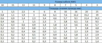
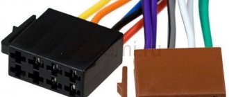
Any alarm equipped with auto-start is usually equipped with 5 power terminals:
Cord 3 here is the control one; it is connected to the starter terminal. And on the blue wire, that is, on terminal 15/2, the voltage may disappear when the starter is running, or it may remain on it all the time. When setting up, select one option.
VAZ 2101-2107 cars have their own characteristics. The coil of the additional relay shown in the diagram cannot be connected to the ignition cord going to the standard relay. The line is simply not designed for additional load!
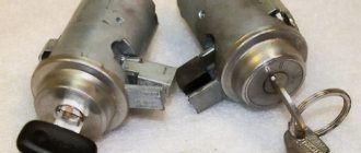
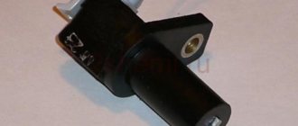
Let's see what the ignition switch looks like in reality:
If you really need autostart, the starter cord (red) will have to be cut. Let's list what the correspondence between the lock and alarm cords looks like. The alarm cable will be indicated on the left:
- Green – free;
- Blue – free;
- Red – pink;
- Black-yellow thick – red (tap to starter);
- Black-yellow thin – red (bend to the lock);
- Yellow - blue thick.
In theory, everything turns out simple.
Of course, you can install the autostart system yourself. But it is better to entrust this task to a professional electrician. The three cords leading to the alarm must carry significant current. In new VAZ models the number of these cords will be no less.
Conclusion
The turn relay is a small but extremely important component of a car's warning light system. It allows the driver to be more predictable for other road users, which, of course, has the best effect on traffic safety and, to some extent, comfort. If the relay fails, the problem cannot be ignored under any circumstances. Fortunately, the relay is not an expensive component of lighting systems, so a car enthusiast can take two devices at once with almost no loss of budget - the second one will be in the trunk, garage or at home in reserve. This is exactly what we advise you to do.
Purpose of the turn relay
The Traffic Rules in force in Russia clearly state that when making maneuvers, it is necessary to turn on the direction indicators, and in their absence, indicate the direction of movement with your hand. However, now most cars and motorcycles are equipped with turn signals, so you rarely need to use your hands to indicate the direction of travel.
When turned on, the direction indicators flash, that is, they light up and go out at certain intervals, so they attract the attention of other road users, and it is quite difficult not to notice the turn signal being turned on. The blinking of direction indicators also serves another role - it does not allow drivers to confuse their activation with the activation of brake lights or the activation of side lights.
Periodic turning on and off (that is, the same blinking) of the direction indicator lamps is realized using a simple device that is part of the vehicle's electrical system - a turn relay, which is often simply called a breaker or breaker relay.
The breaker relay included in the turn signal circuit performs three functions at once:
- Supplying electric current to the direction indicator lamps (that is, turning on the “turn signals”);
- Ensuring intermittent operation of the direction indicator lamps (their blinking);
- Creation of characteristic clicks, signaling to the driver of the car that the direction indicators are working.
In cars of the Volzhsky Automobile Plant of various generations and models, several types of turn relays are used, which have different operating principles and characteristics.