The electrical equipment is made according to a single-wire circuit - the negative terminals of sources and consumers of electricity are connected to the car body, which acts as a second wire.
Electrical circuit diagrams for VAZ2115-20 (without engine control system components) and 2115-01 are shown in Fig. 7-1 and 7-2.
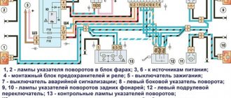
Rice. 7-1. Electrical diagram of VAZ-2115-20 cars: 1 – block headlights; 2 – fog lights; 3 – air temperature sensor; 4 – electric motor of the engine cooling system fan; 5 – blocks connected to the wiring harness of the ignition system; 6 – engine compartment lamp switch; 7 – block for connection to a single-wire type audio signal; 8 – sound signal; 9 – washer fluid level sensor; 10 – front brake pad wear sensors; 11 – oil level sensor; 12 – generator; 13 – engine compartment lamp; 14 – coolant temperature indicator sensor; 15 – starter; 16 – battery; 17 – relay for turning on fog lights; 18 – coolant level sensor; 19 – brake fluid level sensor; 20 – reverse light switch; 21 – windshield wiper gearmotor; 22 – oil pressure warning lamp sensor; 23 – block for connecting to the rear window washer electric motor; 24 – windshield washer electric motor; 25 – instrument cluster; 26 – mounting block; 27 – brake light switch; 28 – ignition switch unloading relay; 29 – ignition switch; 30 – glove box lighting lamp; 31 – switch for the glove compartment lighting lamp; 32 – rear window heating switch; 33 – fog light switch; 34 – fog lamp switch; 35 – external lighting switch; 36 – alarm switch; 37 – steering column switch; 38 – instrument lighting regulator; 39 – hydraulic corrector scale illumination lamp; 40 – socket for a portable lamp; 41 – side direction indicators; 42 – switches in the front door pillars; 43 – canopy for individual interior lighting; 44 – electric heater fan; 45 – additional resistor of the electric heater fan; 46 – heater electric fan switch; 47 – backlight lamp for the electric heater fan switch; 48 – backlight lamp for heater control levers; 49 – display unit of the on-board control system; 50 – trip computer; 51 – switches in the rear door pillars; 52 – block for connection to the clock; 53 – electric fuel pump with fuel level sensor; 54 – ashtray lighting lamp; 55 – cigarette lighter; 56 – trunk lighting; 57 – trunk light switch; 58 – interior lamp; 59 – parking brake warning lamp switch; 60 – external rear lights; 61 – internal rear lights; 62 – plugs for connecting to the rear window heating element; 63 – license plate lights; 64 – additional brake signal.
Conventional numbering of plugs in the blocks: A – block headlights; B – electric fuel pump block; C – blocks of the mounting block, ignition switch, windshield wiper gearmotor; D – interior lamp.
The diagram does not conventionally show that in the instrument panel wiring harness the second ends of all wires of white, black, orange, white with a red stripe and yellow with a blue stripe are connected to each other at the same points
Rice. 7-2. Electrical diagram of the VAZ-2115-01 car: 1 – headlights; 2 – fog lights; 3 air temperature sensor; 4 – generator; 5 – electric motor of the engine cooling system fan; 6 – fan motor activation sensor; 7 – engine compartment lamp switch; 8 – block for connecting to a single-wire audio signal; 9 – sound signal; 10 – oil level sensor; 11 – front brake pad wear sensors; 12 – washer fluid level sensor; 13 – spark plugs; 14 – ignition distributor sensor; 15 – switch; 16 – carburetor solenoid valve control unit; 17 – carburetor solenoid valve; 18 – carburetor limit switch; 19 – speed sensor; 20 – starter; 21 – battery; 22 – relay for turning on fog lights; 23 – coolant level sensor; 24 – brake fluid level sensor; 25 – reverse light switch; 26 – coolant temperature indicator sensor; 27 – engine compartment lamp; 28 – windshield wiper gearmotor; 29 – oil pressure warning lamp sensor; 30 – block for connecting to the rear window washer electric motor; 31 – windshield washer electric motor; 32 – ignition coil; 33 – instrument cluster; 34 – mounting block; 35 – brake light switch; 36 – blocks connected to the injection system wiring harness; 37 – ignition switch unloading relay; 38 – ignition switch; 39 – glove box lighting lamp; 40 – switch for the glove compartment lighting lamp; 41 – rear window heating switch; 42 – fog light switch; 43 – fog lamp switch; 44 – external lighting switch; 45 – alarm switch; 46 – steering column switch; 47 – instrument lighting regulator; 48 – hydraulic corrector scale illumination lamp; 49 – socket for a portable lamp; 50 – side direction indicators; 51 – switches in the front door pillars; 52 – canopy for individual interior lighting; 53 – electric heater fan; 54 – additional resistor of the electric heater fan; 55 – heater electric fan switch; 56 – backlight lamp for the electric heater fan switch; 57 – backlight lamp for heater control levers; 58 – display unit of the on-board control system; 59 – trip computer; 60 – switches in the rear door pillars; 61 – block for connection to the clock; 62 – electric fuel pump with fuel level sensor; 63 – ashtray lighting lamp; 64 – cigarette lighter; 65 – trunk lighting; 66 – trunk light switch; 67 – interior lamp; 68 – parking brake warning lamp switch; 69 – external rear lights; 70 – internal rear lights; 71 – plugs for connecting to the rear window heating element; 72 – license plate lights; 73 – additional brake signal.
Conventional numbering of plugs in the blocks: A – block headlights; B – electric fuel pump block; C – blocks of the mounting block, ignition switch, windshield wiper gearmotor; D – interior lamp (see electrical diagram of the VAZ-2115-20 car).
The diagram does not conventionally show that in the instrument panel wiring harness, the second ends of all wires of white, black, orange, white with a red stripe and yellow with a blue stripe are connected to each other at the same points.
For engine management system connections, see the separate Multiport Fuel Injection Engine Management System Maintenance and Repair Manual.
Most power supply circuits for vehicle electrical equipment are protected by fuses. The battery charging circuit, the ignition and engine start circuit, the generator (with the exception of the excitation winding), the headlight switch relay winding and the door lock system relay are not protected by fuses.
Before replacing a blown fuse, find out the cause of its burning and eliminate it. When troubleshooting, it is recommended to look at the information listed in the table. 7-1 the circuits that this fuse protects.
Fuse no.*
Protected Circuits
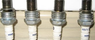
Complete electrical diagram of the VAZ 2114 with decoding
The complete package of electrical equipment of the VAZ 2114 can be divided into two types. The fundamental differences are due to changes in equipment depending on the year of manufacture and equipment of the car. In this case, the entire drawing can be divided into several zones.
- The engine compartment is responsible for providing voltage to sensors and instruments located directly inside the engine compartment.
- Salon compartment. The part is primarily used to connect the front and rear compartments.
- Instrument panel assembly. The pinout is displayed directly on the controls and dashboard. All elements of the on-board network are combined here and connected to buttons or indicators.
- Stern joint. The small module combines chain elements located at the rear of the machine. Typically, the segment is subject to frequent damage, which is due to the constant transportation of goods in the luggage compartment. When moving over obstacles, loads can damage sensitive equipment.
You can also separate small units – these are door units, windshield wipers and others. For ease of perception, each beam is considered separately.
VAZ 2114 instrument panel pinout
The terminals of all vehicle equipment are concentrated here. Due to the fact that the unit is located under the dashboard and is subject to constant condensation or fogging, some users treat it with hot melt adhesive. Even a thin coating can reliably protect the device from water ingress.
Elements are connected to devices or controls:
- 1 – switch key for heated rear glass;
- 2/6 – fog light switches, for rear/front module;
- 3 – plastic block for activating head optics and turn signals;
- 4 – fuse block;
- 5 – wiper mode switch;
- 7 – on-board system indication;
- 8 – supply voltage to the additional harness;
- 9 – dashboard;
- 10 – “male” for powering the on-board computer;
- 11 – terminal to the ignition device;
- 12 – for door wiring;
- 13/14 – fuses;
- 16 – ignition break;
- 17 – stove motor;
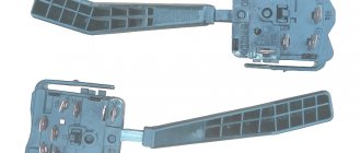
- 18 – secondary resistance of the stove;
- 19 – current supply to the ignition unloading relay;
- 20 – protective relay for rear fog lights;
- 21 – starter fuse relay;
- 22 – remote socket for a portable lamp;
- 23 – power supply for the cigarette lighter;
- 24 – for illumination of the glove compartment;
- 25-27 – illuminators;
- 28 – stove switch;
- 29 – tidy lighting with rheostat;
- 30 – stop switch;
- 31/32 – horn/hazard warning switch, respectively;
- 33 – backlight of the stove panel;
- 34 – fuse;
- 35 – protective relay for seat heating elements;
- Ш1/4 – mounting block jumpers;
- X1/2 – dashboard controls;
- A – protective ground output (usually black).
Installation of an electric window regulator (ESP) on a VAZ-2114
The most popular window lift systems on the VAZ-2114 are rack and pinion types. Their connection is carried out according to the scheme described below.
- Disconnect the on-board power supply from the supply. To do this, remove the terminals from the battery, you can close one - the negative one.
- All the wires that come with the ESP on the VAZ-2114 are twisted together into a bundle.
- The mounting block is removed by unscrewing the screw that controls the position of the latch.
- A wiring harness is mounted into the block in place of the connector of the block.
- The door trim is removed.
- The ESP is installed, along with all the buttons and keys.
By the way, you can make a choice if you wish. Install the buttons and keys that control the window regulator either on the door panel or on the control unit. In the latter case, you will need an additional wire and knowledge of the theory of pinout of the ESP button.
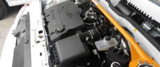
Electrical equipment of the front of the car
The following is a breakdown of the front cable bundle, excluding fog lights:
- 1 – output terminals of the starter contact group;
- 2 – battery, connection of power cables;
- 3 – standard “father” of the generator;
- 4 – blocks for connecting the power conductors of the battery and generator to the front assembly of electrical equipment;
- 5 – part of the fuse mounting block;
- 6 – standard horn;
- 7 – sensor that measures the temperature of antifreeze in the power plant;
- 8 – standard sensor for measuring the washer fluid residue in the tank; when activated, the corresponding indicator on the device lights up;
- 9/10 – left and right headlights, respectively;
- 11 – external thermometer;
- 12 – standard reverse gear lamp switch;
- 13 – drive of the electric fan of the generator;
- 14 – connector to the ignition system module;
- 15 – in the VAZ 2114 scheme the injector is not used, it is used only for the carburetor;
- 16 – electronic brake fluid level sensor; in case of a critical drop, an exclamation mark lights up on the instrument panel;
- 17 – built-in oil level sensor in the crankcase compartment of the power plant; when activated, the red light on the instrument panel lights up;
- 18 – similar for the engine cooling system;
- Ш5-8 – mounting block connectors;
- A1/2, B1/2 – grounding terminals.
Reworking the low beam button
As already mentioned, the button for turning on the low beam and the button for the dimensions of the VAZ 2114 are combined and located in pairs. Their main drawback, which most car enthusiasts point out, is the absence of a power-on LED on the low-beam headlight button.
This problem is quite serious, since very often it becomes unclear whether the headlights are working or not (especially during daylight hours). You can solve this by upgrading the button yourself.
For this you will need:
- a button that will be redesigned;
- the second button is the same - donor;
- soldering iron or (better) soldering station.
The button modification should be carried out according to the diagram shown here. Resoldering the LED itself from one board to another is highly not recommended, since this requires a soldering station equipped with a hair dryer, a special flux and high skill in working with them.
First, we need to remove the main button from the car panel (how to do this has already been discussed above).
After it is removed and disconnected from the wires, perform the following operations:
- remove the keys by prying them off with a flat screwdriver;
- we disassemble the body of the buttons by pressing the latches with a screwdriver (the buttons themselves at this moment must be in the “on” position);
- we see that the sidebar button has two diodes (backlight and indication), and the low headlight button has only a backlight button;
- remove a pair of legs and a pair of contacts from the donor button;
- we rearrange them into the free spaces on the working button;
- remove the board from the donor button with two diodes and insert it into the working button instead of the board with one diode;
- solder the board to the legs that were added;
- make a hole in the button cover (this can be done with a sharp knife or simply punched with a flat screwdriver).
The junction of the newly installed legs and the new board must be well soldered. Otherwise, the button may quickly fail or not work correctly.
After all these operations have been completed, all that remains is to assemble everything in the reverse order and install the upgraded button in its place (during installation, it is important that all the mini-latches on the case fall into place).
Wiring diagram VAZ 2114 injector: decoding of rear harness contacts
Here are the conclusions of the equipment located in the rear of the vehicle:
- 1 – output of the mounting unit;
- 2 – windshield heater;
- 3 – electric drive of the rear wiper gearbox;
- 4 – diodes for illuminating the stern license plate;
- 5 – license plate illuminator directly, some users connect diode strips here for better lighting;
- 6/7 – illuminated direction indicators, for the left and right sides, respectively;
- 8 – lamp for individual illumination of useful space;
- 9 – interior lighting lamp, usually located in the ceiling, above the steering seats;
- 10 – handbrake lever position indicator;
- 11/12 – left and right side lighting lamp;
- 13 – power supply to the additional brake light indicator;
- 14-17 – group of interior lighting switches located in the door pillars;
- Ш9 – terminal block of the fuse mounting device;
- A1 – license plate grounding;
- A2/7 – standard grounding points.
Schematic diagram of the VAZ 2114 stove: a separate line responsible for powering the windshield wiper
A small cable harness responsible for powering and controlling the cabin air supply box. There is also a power supply for the windshield wiper:
- 1 – part of the installation site exit;
- 2 – sensor for monitoring lubricant pressure in the crankcase compartment of the power plant;
- 3 – power lines of the aft windshield washer motor;
- 4 – voltage to windshield washer drives;
- 5 – diagram of the electric motor for windshield wipers;
- Ш11 – terminal for connection to the installation site;
- A – grounding terminals of the wiring section.
Electrical connection diagram for VAZ 2114, additional segment
Here are grouped auxiliary equipment that is not related to the power plant or on-board computer of the car:
- 1 – contact group of wiring from the doors to the instrument panel block;
- 2 – a similar terminal intended for connecting heated seat devices for the driver and front passenger;
- 3/4 – central locking drive, sections of the front left and right doors, respectively;
- 5/6 – contact blocks of the front right and left speakers, respectively;
- 7 – electronic central locking control unit;
- 8/9 – connecting door parts of electrical equipment to the auxiliary left beam;
- 10 – terminal for connecting the standard speaker system;
- 11 – “mother” of doors to the right wiring harness for connecting electrical equipment;
- A1 – connection of grounding electrical wiring.
Physically, the output is connected to the dashboard, with a contact group located near the hood opening handle. The corresponding fuse is also located here.
We study the designation of icons on the instrument panel of the VAZ 2114
The VAZ 2114 dashboard is the main information block, which displays data on the current functional state of the car. It is located on the dashboard, directly in front of the driver's seat.
Tidying VAZ 2114, 2113,2115
The panel itself contains three types of elements:
- Indicator lights indicating the amount of consumables required for the operation of the car - gasoline, oil, brake fluid, etc.;
- Speedometer and tachometer;
- A control element for switching the speedometer operating mode.
Also, the concept of “instrument cluster” usually includes levers for turning on turn signals, buttons for controlling headlights, heater, and other communications of the car.
The VAZ 2114 dashboard diagram looks like this:
Instrument panel (diagram)
From this article you will learn the designation of the icons on the dashboard of the VAZ 2114, the reasons for the indicators to light up, as well as the measures that need to be taken to eliminate the problems that have arisen.
- MAIN PANEL ELEMENTS
- INDICATOR BUGS
- BUTTONS ON THE INSTRUMENT PANEL
VAZ 2114 wiring diagram: section of the right front door
The cut is a simplified concept due to the minimal amount of equipment. The most budget version is completely absent.
- 1 – “mother” of the rear harness, suitable for the door wiring;
- 2 – power supply to the electric motor for the front passenger window;
- 3 – terminal block to the standard door speaker;
- 4 – door lock servo motor (part of the central lock);
- 5 – power switch and power window drive mode switch;
- A – grounding bus.
Wiring diagram VAZ 2114: driver's door
A larger section of standard on-board wiring:
- 1 – contact group for connecting to the wiring of the additional bundle;
- 2 – similar output to the aft left beam;
- 3 – electric window motor drive;
- 4 – standard output of the block to the front speaker of the standard acoustic system;
- 5 – door lock drive;
- 6/7 – power window control buttons, for left and right, respectively;
- A1 – standard protective grounding terminal.
Wiring diagram VAZ 2114 injector - a separate section of seat heating equipment
A specially dedicated section of on-board wiring responsible for powering, activating and adjusting seat heater devices. Here is a detailed description of all structural elements:
- 1 – driver’s seat heater;
- 2 – output to the terminal block of the dashboard;
- 3 – separate connector for the driver’s door, wire supply to the control button;
- 4 – heating element of the front passenger seat;
- 5/6 – adjustment key for the element specified in paragraphs No. 1 and 4;
- A1 – grounding wire, fastened with a bolt to the car body.
Euro emergency warning button VAZ 2115
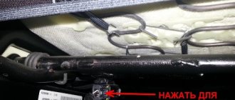
I finally decided to make my own emergency signal button (or, more simply, an “emergency light”). In our Russian VAZs 2113-2115 is located in a very inconvenient place. To be more precise, behind the steering wheel. And in the modern rhythm of life, when it has become customary to “blink” the emergency lights as a sign of greeting or gratitude, such an arrangement is unacceptable.
I started by ordering “relay HLS-4453(18F)-4, DC12V, 4 groups of contacts. 5A" from the site www.ekits.ru/index.php?product >
Then I bought 1.5 wires, many wrote that they needed exactly these, but they were too big, 0.75 above the roof would be enough. I bought, as the common people say, “PAP” and electrical tape. Next, a soldering iron in your hands and a diagram in front of your eyes.
Everything is quite simple, but you waste a lot of time, if you assemble it for the first time, it took 3 hours to assemble it from scratch)) Then INSTALLATION: I forgot to take most of the photos, so I took them from other users: www.drive2.ru/l/363984/ and www.drive2 .ru/l/1042092/
We disassemble the instrument panel and remove the casing.
We remove the casing and disassemble the old emergency button and move the wires to a place convenient for us.
We begin to slowly collect our miracle. We put the button in a place where it will be more convenient for us to use it.
We assemble the wires from the new button to the old one according to the diagram.
Just in case, I tied it with electrical tape so that it wouldn’t fly out of the connectors on bumps. Next, install the Din rail in the free space. And tighten the nut and bolt to 5.
We install the block with the relay on it.
And finally, we begin to connect to the dimensions and the dashboard itself.
I draw your attention to the fact that according to the diagram there are two minuses, they can be combined into one, but I made them in 2 different ones and connect them to the dimensions block, there are 2 black wires, both minuses, I did both)) And the dimensions of the new one I connected the buttons to the white wire on the block.
Next we move to the dashboard itself. We unscrew it, it is attached to two self-tapping screws. At the back we see two blocks, white and red, we need the red one and connect the wire there that goes according to the diagram into an empty socket.
This is so that the red triangle glows (you can do without it). Looks really cool. PS Some panels do not have a triangle light bulb, you have to buy one and screw it in.
In the end, this is how my button looks
Spent about 2 hours on installation.
Everything you need for the euro button:
1. Relay HLS-4453(18F)-4, DC12V, 4 groups of contacts. 5A — 106 rub. 2. Block for relay HLS-4453(18F) - 62 rub. 3. Euro button - 91 rub. 4. Block for the euro button - 50 rubles. 5. Din rail - 7 rubles. 6. Dads - 7 pcs. — 40 rub. (we buy 6 large and 1 small). 7. Wires 1.5 - 7 meters * 8.2 rub. = 58 rub. (I repeat, it’s better to take 0.75 wires and 7 meters was not enough for me, take 8 meters). 8. Electrical tape - 15 rubles.
To be honest, the standard emergency lights are boring; it’s inconvenient to reach over the steering wheel when you need to thank someone. I ordered a “Relay for installing the Euro emergency stop button VAZ 2108-2115” from VAV-21123. A week later the package arrived. I installed it without much difficulty, disassembled the panel, and connected it according to the diagram. I dragged the standard corrugation with emergency signal wires from the steering casing to the on-board computer, and the new emergency signal relay was also located there. The hazard warning light icon on the dash was connected to contact D on the button (oddly enough, the light bulb was already in the dash). I placed the button behind the heated glass, and moved the heated glass downwards, then next to the heated glass I will put a button for heated mirrors (once I buy these mirrors). Thanking drivers has become much more convenient. Price: The emergency kit itself is 665 rubles. including delivery Terminal for connecting the delta on the dashboard - 2p. Plug for a hole in the steering wheel casing - 10 rubles. PS: If you liked it, click like
Price tag: 677 ₽ Mileage: 56800 km
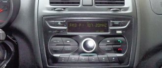
Pinout of on-board computer VAZ 2114
In standard drawings of electrical equipment, the BC block section is missing due to its uselessness. Initially, it is assumed that the motorist will not independently repair or maintain the complex control unit. But some users still take risks and install the system themselves. In older versions of cars, such a module is missing or insufficient for comfortable operation of the car in its modern form.
To connect wires to the module, you will need to buy a standard 9-pin header and connect the following wires to it:
- 1 – green wire comes from the fuel consumption sensor;
- 2 – the ignition cylinder is powered through an orange cable;
- 3 – power core from the battery, usually a red wire with a white stripe is supplied;
- 4 – grounding or ground, standard color – black;
- 5 – 6k line, usually a gray wire;
- 6 – Mute – green shell with a red line;
- 7 – the backlight in the standard pinout is output from the marker optics key;
- 8 – a sensor that displays the remaining fuel in the car’s gas tank can be connected directly.
How to prevent electrical equipment breakdowns?
In order for the VAZ 2114 pinout to be required as rarely as possible, the user is required to follow a number of simple rules and recommendations.
- Periodically treat all metal parts with special oil. In this case, it is first necessary to clean the copper patches from oxides and traces of corrosion. Such lesions provoke a deterioration in the transmission of signals, which can be perceived by the car as a breakdown.
- Every 20-30 thousand kilometers, check all equipment and plastic plugs for looseness or reduced fastening rigidity. With constant vibrations typical of vehicles, plastic clamps can fail and cause breakdown.
- Monitor the correct battery charge and the serviceability of the generator. Some machine devices do not work correctly when there is a strong voltage drop.
- Every 40,000 km, check the condition of the wires themselves. With constant use, the braids of the power cores may crack or dry out, which increases the likelihood of a short circuit in the on-board lines. This may also cause a fire.
Button for dimensions and low beams of VAZ 2114: features and replacement
For greater convenience, the button for turning on the low headlights and the button for turning on the dimensions of the VAZ 2114 are made in pairs and are located on the European panel of the car.
Both of them are equipped with additional built-in LEDs (two for backlighting, as well as an indication diode for side lights). As a rule, there are no problems with the operation of these buttons, but if necessary (for example, if they break), you should know how to replace them.
Everything is done in the following order:
- Remove the plug under the button panel (it can be removed simply by hand, without tools).
- Push the buttons into the interior by pressing them from the inside.
- Gently pull the button, rocking it slightly, and remove it from the block.
- Install a new button into the block.
- Place the buttons back into the panel.
As you can see, the replacement can be done almost instantly, without applying any great effort or using a special tool.
Another important point that should be highlighted is the pinout of the VAZ 2114 size button. It may be needed, for example, when replacing an old type button with a button for a Europanel.
You can see it most clearly in the following diagrams: for old type buttons
for new type buttons All letters indicated in the diagram correspond to the output contacts of the buttons and have similar markings to them, and the colors of the wires are indicated by letter abbreviations.
Also, the pinout of the VAZ 2114 light switch button can help when troubleshooting problems in the operation of the buttons themselves, for example, if the backlight of one of them does not work.
In this case, it should be taken into account that the contacts:
- 6-V or 5-V - responsible for the operation of the low beam indicator;
- А-В — illumination of the low-beam headlight button;
- С-D — indicator for turning on dimensions;
- E-D — illumination of the button for turning on the dimensions.