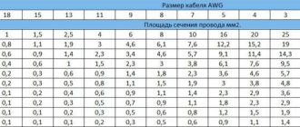
ISO pinout or pinout is the identification of each electrical connection pin in a connector or diagram according to its corresponding numbering and functionality. The speaker system of any manufacturer is connected to the standard ISO connectors of the car. Proper pinout will help you get a good sound at the output and not burn out the connectors with voltage. You can understand the wires using standard diagrams. You can install any brand of car radio without having specialized knowledge in electrical engineering. When working with non-standard connectors, do not forget about safety. “Ring” the wires using a multimeter.
What is iso
ISO is an international organization that develops standards and regulations for various industries. The abbreviation sounds the same in all languages. A Russian manufacturer working in accordance with standards labels its products with the abbreviation “ISO” or “ISO”. All well-known developers of car radios equip their products with two types of standard plugs. Each looks like an eight-pin rectangular connector.
Precautionary measures
You need to understand that incorrectly connecting the car radio can lead to unpleasant consequences:
- Breakdown of the radio;
- Deterioration in sound quality;
- Wiring short circuit;
- In rare cases, if you connect the radio to the battery incorrectly, you can quickly discharge it. Sometimes this can cause a fire.
In order not to waste your time, you can use the services of a car repair shop, but you need to be prepared to spend a certain amount that the service will charge for connection. In addition, it is worth considering that the cost of connecting a car radio to a foreign car (for example, Toyota) will be higher. The brand of the car radio is also taken into account. Thus, a Pioneer radio (which is the most common and beloved among motorists) will cost less than a Sony or Kenwood radio.
But if a car enthusiast has a desire to understand the device, the ability to spend a couple of hours and, no less important, the desire to save a decent amount of money, then the rest of the article will describe in detail how to connect a car radio according to the colors of the wires.
Pinout of a standard Euro connector
A Euro connector is a standard plug used in most countries around the world. When connecting equipment, you may encounter non-standard wires tangled in a bundle. This problem is solved by purchasing adapters and pinouting the radio chips.
Standards 1din and 2din
Speaker system connectors come in two types: non-standard ones from the manufacturer, mostly pin-type, and standardized European ones, which are located at the back. Installation of equipment with a special audio connector from the manufacturer will require the use of a special proprietary connector. If the plug is ISO, then you can connect to it directly. There are two types of Euro connectors: 1din and 2din, the difference is in the height of the car radios. The two-block one is twice as tall; it is not connected to all cars, because there is no space on the panel for the required dimensions.
Radios with European 1din are the most common.
When installing car radios, wires with a small diameter of 1.5-2 mm are used, for power lines - with a large cross-section. Failure to follow these simple rules will distort the sound and damage the equipment.
| № 1 | — |
| № 2 | — |
| № 3 | — |
| № 4 | Constant power |
| № 5 | Antenna power |
| № 6 | Backlight |
| № 7 | Ignition |
| № 8 | Weight |
Manufacturers in Japan, the USA and some Chinese use the 2din standard.
Upper power connector A
The plug is used to supply electricity to the receiver, antenna and amplifier, as well as when it is necessary to control the backlight or turn off the sound signal. Standard color markings are used. Outputs 1-3 and 6 are not used in low- and mid-price segment speakers; they are intended for additional options for high-end products.
Connection types
- The first is the connection in the socket of wires of two colors, yellow and red, turning the receiver on/off does not depend on the ignition. The method is inconvenient because it predisposes the battery to discharge if the acoustics are not turned off;
- The second wire is connected through the ignition switch, the yellow wire is connected to the on-board computer.
Functional purpose of the receiver outputs
| ANT | The connector is used if the car has a retractable antenna |
| Remote | Multiple speakers can be connected |
| Illumination | Allows you to change the intensity of the device's glow |
| Mute | Adjusting the sound |
| A4 | Turn on/off |
Pinout of radio ISO connector
| A 4 | Color yellow | Battery + Power |
| A 5 | Color blue | Antenna. |
| A 6 | Color orange | Backlight |
| A 7 | Color red | Ignition, 12V. When disconnected, reset settings to factory settings. |
| A 8 | Color black | Acoustics |
Bottom speaker connector B
Used to connect amplifiers (2 cables each). The sound of the equipment depends on whether all connectors are connected correctly. The main thing is not to confuse them, otherwise the acoustics will be of poor quality.
Rules for connecting speakers by color marking of wires
| Color white | Left front |
| Color grey | Right front |
| Color green | Left rear |
| Color violet | Right rear |
Removing an old car radio
So, the treasured radio is waiting in the wings. It's time to get rid of your old audio system. At first glance, it may seem that this procedure is not complicated. By and large, this is true. However, there are a number of nuances that it is advisable to take into account during dismantling.
Note for you: How to remove a radio without pullers and keys
At the initial stage, in order to avoid damage to the panel elements, it is necessary to find out how the radio is secured in the niche.
Depending on the type of car audio system, there are several mounting methods:
- using flexible metal tongues;
- using plastic clips;
- using a screw connection.
As a rule, if we are talking about a standard radio, there is a last method of fixation. Often, the manufacturer, pursuing an aesthetic goal, masks the heads of screws or screws with plastic caps. Dismantling such a radio should not cause serious difficulties. To do this, it will be enough to unscrew the screws and gently pull it out.
The situation is somewhat different when the radio is located inside a metal casing. In this case, special keys will be required to remove the radio. Hardly anyone remembers their existence when this kind of need arises. However, all radios of the presented type are equipped with them.
The principle of fixing such a radio is not very complicated. Flexible metal tongues with a protruding part are attached to its side walls. On the casing, in a strictly verified place, there are special recesses. The aforementioned tabs go into them, rigidly fixing the radio in the casing.
If you don’t have a key, you can use two thin metal plates to remove it. To do this, you need to insert each of them between the frame and the radio, thereby squeezing out the metal tabs.
After this, you should pull the radio towards you, turning it slightly in different planes. It should be noted that this kind of tricks of manufacturers is nothing more than measures of protection against lovers of easy money.
In addition, radios can be installed in the panel using plastic clips. With this method of fastening, it is important to prevent distortion of the plastic frame. To avoid damage, the clips should be released gradually and evenly, avoiding distortions.
Useful to read: What is a diesel intercooler: principle of operation and causes of failure
With any method of fixing the radio, its dismantling must be done carefully so as not to damage the integrity of the connecting wires and contacts.
Dual ISO connector
The standard audio systems of some cars are connected with a double plug. The pinout of connectors for them is standard. The contact halves are connected to each other by a durable plastic jumper and secured with a special clamp. For correct installation, a guide groove is used, which prevents the plug from being installed in the wrong position.
The black one connects a current source to the radio, the brown one for acoustics.
How to connect your phone to Pioneer
The presented type of car radio does not meet all the requirements of its owners. For example, it is not possible to connect a phone to it without carrying out a number of actions. Let us dwell on this in more detail, since the presented topic has not lost its relevance.
To carry out such a procedure, you will first need to make a so-called linear input. The presence of such an analog input will allow you to connect a number of devices to the radio, including a telephone. Let's look at the most common method of installing a linear input.
Adapters for ISO connectors
Cutting off a non-standard standard plug and connecting the wires directly is not recommended, because over time the connection will become loose, may oxidize, you will have to solder not only the wiring, additional repairs will be required, replacing blown fuses. Sometimes there are acoustics with three outputs, but they have standardized markings and electrical circuits that allow you to connect standard cables to the device using pinouts. You can buy any type of adapter for ISO connectors from one model to another.
The car may not be equipped with connectors, then you need to connect the radio connector to the cable directly. This is done by twisting, soldering, or using a terminal block that does not require subsequent insulation. When twisting and soldering, heat shrink tubing is used for safe use of the equipment.
Wire marking
To correctly connect the wires in the Pioneer radio, first understand the marking features. The equipment kit includes connectors for connection, consisting of two contacts. Each has 8 wires. The power circuit is connected using one connector. The second one is needed for acoustics.
Car radio wires
Pioneer connects in two ways. You need to purchase a special connecting adapter. Some do this: they disconnect the connectors from the wiring and connect them by twisting.
Pinouts for various brands of cars and radios
Before getting started, read the instructions for the receiver, and also pay attention to the markings and features of the product itself. The pinout of radios is influenced by standard connectors in different cars.
Pinout diagram for ISO connectors for pioneer radios
Connecting the acoustics of this well-known brand, which is popular among motorists, has some features. Be sure to read the installation manual before starting work. Installation is simple, the main thing is to understand the purpose of each color. In addition to the instructions, the kit includes two “chips” with 4 pairs of contacts: for power and acoustics.
The pinout of the plug has 10-20 outputs, the functionality of each connector varies depending on the model. The KEH series is characterized by the following circuit: No. 1 - antenna, No. 2 - ignition, No. 3-6 and 8-11 - amplifiers. To avoid confusion, please read the instructions carefully.
In order not to burn out the acoustics, before connecting the speakers you need to connect the radio, check that it lights up and switches.
toyota
The pinout of acoustics of this brand is carried out according to standard diagrams. It is optimal to choose a power supply system from a battery, in this case there is no risk of its discharge.
ISO connector:
| № 1 | A+ |
| № 2 | GND |
| № 3 | BAT+ |
| № 4 | Backlight |
| № 5 | Antenna |
| № 6 | Speakers (RR+, RR-, RF+, RF-, LF+, LF-, LR+, LR-) |
sony
When connecting the radio, standard circuits are used.
| № 1 | ANT |
| № 3 | L.R. Line output |
| № 4 | GND. Line output |
| № 5 | R.R. Line output |
| № 6 | CD–LCH |
| № 7 | CD - GND |
| № 8 | CD–RCH |
| № 9 | CD - Reset |
| № 10 | CD – CD clock out |
| № 11 | CD – DSPL select |
| № 12 | CD – data out |
| № 13 | CD – clock in |
| № 14 | CD – data in |
| № 16 | A+ |
| № 17 | GND |
| № 18 | ANT GND |
| № 22-27 | Speakers (LF-, LR+, RF-, RR+, LF+, LR-, RF+, RR-) |
| № 28 | Mute |
| № 29-30 | Speakers (LF-, LR+, RF-, RR+, LF+, LR-, RF+, RR-) |
| № 31 | ANT CONT |
| № 32 | CD ACC Constant |
| № 33 | AMP Constant |
| № 34 | BUP |
nissan
Universal connector:
| № 1-6 | Speakers (LR+, RR+, LR-, RR-, LF+, RF+) |
| № 7 | A+ |
| № 8 | Backlight |
| № 9 | BAT+ |
| № 10 | Speakers LF- |
| № 11 | RF speaker |
| № 12 | Antenna |
| № 13 | GND |
honda
All models of car radios are equipped with a universal European plug for connection to the socket.
| № 1 | Speaker RR+ |
| № 2 | Speaker LR+ |
| № 3 | Backlight |
| № 4 | BAT+ |
| № 5 | A+ |
| № 6 | Antenna |
| № 7-10 | Speakers LF+, RF+, RR-, LR- |
| № 13 | GND |
| № 14-15 | Speakers LF-, RF- |
bmw
Standard European pinout.
| № 1 | A+ |
| № 2 | BAT+ |
| № 3 | GND |
| № 4 | — |
| № 5-12 | Speakers RR+, RR-, LF+, LF-, RF+, RF-, LR+, LR- |
alpine
Alpine TDE-7823W: 1 – BAT+,
| № 2-5 | Speakers LR-, LR+, RR-, RR+ |
| № 7 | Amplifier |
| № 8 | Antenna |
| № 9 | GND |
| № 10-13 | Speakers LF-, LF+, RF-, RF+ |
| № 5-12 | A+ |
mitsubishi
All models use standard European speaker pinout.
| № 1-2 | Speakers RR+, LR+ |
| № 3 | Antenna control |
| № 4 | Backlight control |
| № 5-8 | Speakers LF+, RF+, RR-, LR- |
| № 10 | A+ |
| № 11 | BAT+ |
| № 12 | Backlight control |
| № 13-14 | Speakers LF-, RF- |
| GND |
Direct connection
So, if you properly understand the connectors and wiring, it will be difficult to make a mistake. Everything should be clear here: take the connector and connect it to the answer. But people love complexity and choose a labor-intensive procedure. Disconnect the wiring from the detachable plugs and connect it, guided by the functionality of the wiring.
Radio chip diagram
After connecting, it is important to carefully insulate the wires to prevent damage due to short circuits. To ensure reliable connections, the wires are secured with a plastic clamp.
In all interiors, there are places for mounting a radio on the consoles or on the instrument panels. In some cars, such places are hidden under a decorative panel. And, before you begin installing the car radio, the panel should be removed by unscrewing it with a screwdriver.
You will get a compartment. From it you need to remove the mating wires, which are necessary to connect the Pioneer car radio to the system. After this, connect the wires or connectors as shown in the photo of the diagram. And only now should the Pioneer be installed in the lot, in its seat.