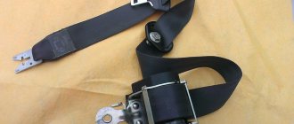
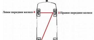
The transfer case is one of the main sources of vibration and noise in the VAZ 21214 and the modernized Urban.
The peculiarity is due not only to the specific design solutions of the unit, but also to the method of attaching the part to the car. So, instead of mounting it on the power components of the body, as is customary in the global automotive industry, engineers implemented a method of communication through silent blocks directly to the floor of the car.
The result is a rapidly collapsing bottom at the points of engagement and “splitting” at speeds above 80 km/h.
One way to relieve stress is to install a transfer case subframe on the Niva. At the same time, the owner will notice a decrease in vibration load, an increase in the natural service life, and also the protection of the transmission.
The disadvantages are the relative complexity of implementing the idea and the ground clearance reduced by 2-3 cm (corrected by a suspension lift).
Manufacturing according to the scheme
Although the market has no shortage of offers, it is possible to save money by making a subframe for Niva 2121 with your own hands according to the drawings.
Drawing 2.
Drawing 3.
Scheme 4.
Fig 5
Fig 6.
In the creation process, you will need a 4 mm sheet of cold-rolled steel 0.525x0.350 m, angles 35x35, 70x50, 70x70 with a length of 0.7 m, 0.4 and 0.4 m, respectively, as well as a 0.73 meter channel 16. Used as fasteners bolts M8, M10, M12x1.25 and M12x1.5.
Materials, tools and drawings
The protection is mainly used for models 21214, 2121, 21213, which have vibration problems. To assemble a subframe on the field with your own hands for a transfer case, you will need metal channels, angles, bolts and a sheet of thin metal as the main materials. In addition to materials, you need to get diagrams or a drawing of the subframe. The simplest design consists of two transverse parts and two crossbars that connect them. Tools worth preparing:
- grinder;
- drill;
- measuring instruments - calipers, ruler;
- bank;
- hammer.
To protect against metal filings, you should take protective clothing made of thick fabric.
There are several design options, so the number of channels and angles may vary depending on the drawing.
Standard tool
- angle grinder;
- drill;
- caliper and ruler;
- core;
- hammer.
An alternative tuning option is permissible using not corners, but a square profile with a section of 60x30 or 40x25.
There are ideas of placing the RC and the checkpoint on the same “frame”.
Preparation.
1. After the initial preparation of the elements, finishing processing and connection into a single structure is carried out: 1. In the channel, in accordance with the diagram, rectangular windows are cut out, ending no closer than 0.8 cm to the edge of the edge. Bevels (chamfers) are eliminated;
2. In corners measuring 70x50 or 70x70, holes are made for bolted connections, after which they are tacked by welding.
3. Corners of 35x35 cm are fixed to the lower edge of the channel, to which sheets are welded to protect against impacts and dirt. In the latter, for the purpose of access to the drain plug and regular cleaning, service holes are cut out.3. Corners of 35x35 cm are fixed to the lower edge of the channel, to which sheets are welded to protect against impacts and dirt. In the latter, service holes are cut out in order to gain access to the drain plug and regular cleaning.
Design modification
To strengthen the subframe and reduce the profile height (up to 2 times), it is possible to additionally equip the side shelves of the channel with 4 corners at the level of the hole under the transfer case, followed by cutting off the sidewalls to the corner flange.
Finer tuning is provided by connecting the spar and subframe through couplings/bushings.
Installation of the Niva-Comfort subframe
Video | |
Instructions | |
| 1. Place the gearbox and transfer case in the neutral position, thereby ensuring free rotation of the intermediate shaft. 2. Unscrew the nuts securing the elastic supports of the transfer case on its axles (M10, wrench 17) and the bolt securing the elastic support of the box to its bracket (M10). | |
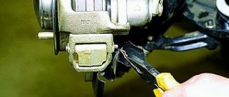
| 3. Unscrew and remove the catalyst thermal protection shield (if there is one) on Niva cars before 2008. Trim as shown in the photo. | 4. Unscrew the transfer case supports from the body and remove them from the axles. 5. Unscrew the box support bracket from the body and remove it. |
| 6. Unscrew the elastic support from the gearbox and remove it (later it will be used as a third support for the transfer case). | 7. Unscrew the two nuts on the rear cover of the transfer case at the level of fastening the bracket of the third support and cut off the rib located between these nuts, ensuring a tight fit of the bracket to the cover. |
| On the fields, the year of manufacture is after 2008. Location of the catalyst (as in the photo) | 8. Remove the catalyst clamp bracket and cut it off as shown in the photo. |
| 9. Thus, a part of it remains at the place where the bracket is attached. | 10. Attach the third support bracket to the transfer case with two nuts. |
| 11. Attach the strips with elastic supports installed on them to the free studs in the body (do not pull the supports to the plates). Before installation, treat the bottom with mastic. | 12. On models before 2008, do not remove the bracket. Unscrew the lower nut securing the bracket on the box on which the clamp of the muffler exhaust pipe is secured to the gearbox. |
| 13.On the elastic supports of the transfer case, on the side opposite to the surface of their mounting, make a 5 mm cut parallel to this surface, thereby reducing their height to maintain the vehicle’s ground clearance. (If these supports are not included). | 14. The supports are placed on the transfer case in such a way that their mounting holes, made asymmetrically, are shifted towards the transfer case body (or with arrows towards the transfer case). |
| 15. Raise the transfer case in any way, for example as in the photo. install the frame on the two free studs securing the box support and the bolt securing the muffler clamp bracket. Secure the frame with nuts. | 16. Install the frame on the two free studs securing the box support and the bolt securing the muffler clamp bracket. Secure the frame with nuts. |
| 17. Lifting the frame by its front part together with the transfer case installed freely on it (for example, a jack), align the holes on the frame with the holes in the side supports installed on the strips. (Place the jack only under the front part of the subframe). | 18. Insert bolts (M10) into the aligned holes and loosen the frame. |
| 19.Tighten the nuts securing the supports with stripes and the nuts on the bolts inserted into them. | 20.Install the third support on the transfer case. Place the gearbox and gearbox in the neutral position, then start the engine and accelerate. |
| 21. If the bracket and support do not match, modify as shown in the photo. | 22. Insert the bolt connecting it to the bracket on the transfer case (M10) into the support and tighten. |
| 23. Secure the transfer case supports to the frame (M8 bolts) (In the event that the distance between the transfer case supports and the bottom of the body is insufficient (they touch the bottom when the frame oscillates), it is permissible to install spacers between the side supports and the strips to which they are attached ). | 24. Install a thermal protection shield on Niva before 2008. |
Installation
For ease of installation, the car is fixed on a lift or above a pit. Pre-preservation of surfaces (attachment points, subframe) is carried out using protective agents, for example, Movil.
The finished product is tried on site individually for each vehicle. 4 holes are drilled along the perimeter of the structure, symmetrical relative to the center line. Having previously loosened the transfer case fasteners.
Having placed the plates on the interior side, as in the photo, the subframe is attached to the side members with M12x1.25 bolts.
The RK brackets are sequentially removed, turned over and freely fixed to the subframe. The position of the shaft flanges is adjusted until minimal gaps are formed by moving the entire structure. Alignment is performed at 3000 rpm with the machine standing.
The bolts are thoroughly tightened.
How to attach
Usually the subframe is made in the form of a frame welded from metal profiles. Aluminum can be used to make the structure lighter. Fastening is carried out using the following parts:
- long studs and nuts
- bolts
- silent blocks
Depending on the type of vehicle, several subframes may be installed, depending on which element relative to the body part should be secured. The middle one is used for the transfer case and supporting the gearbox. The rear one protects the axle gearbox. the front one is necessary for more reliable fixation of the engine.
The shape of the subframes used varies depending on the type:
- square
- H-shaped (there may be different modifications with offset elements)
- in the form of crosses
The subframe has a wide range of advantages. It strengthens the side members, strengthening the car's structure. When installed in the front of the car, it absorbs vibrations from the engine. When installed in the middle part, additional protection of the transfer case and gearbox from impacts is formed. Can be used as a frame for attaching additional devices.
But there are also a number of disadvantages.
When using a subframe, body rigidity increases. This is a good indicator for cars used off-road. But on the highway, this can affect the safety of passengers as a result of an accident, since the deformation area of the body is reduced and the impact force increases many times over. Installation of a homemade structure can be carried out with errors, as a result of which it can become cumbersome and significantly reduce ground clearance.
To make a subframe on a Chevrolet Niva, you need the following set of tools: a hammer, a core, a ruler, a welding machine and an angle grinder.
You will also need some materials:
- steel corner 6*6 and 1.5 meters long
- 2 plates 25*25 and 2 plates 10*20 5mm thick.
- metal profile 40*20 with a length of at least 1.5 m
- 4 bolts 12*1.25 and 4 bolts 10
First, measure the distance where the subframe is attached to the side members in order to drill holes. It is necessary to make 2 on each side for installation. The caps of the bolts that will be used for fastening on the interior side must be welded to avoid twisting.
The transfer case mounting nuts must be loosened in order to mount the subframe. After installation, they must be tightened well again. The transfer case bracket must be attached to the subframe. The box must be positioned so that the flanges of the drive and intermediate shafts are at the same level.
If installed correctly, changes in the control and sensitivity of the suspension will immediately appear.
Production of a subframe in-house according to drawings
To work you will need a certain list of tools. In an ideal situation, everything is done using milling equipment. But if this is not possible, you will need means to protect parts of the body (face, hands). Also a high-power drill, ruler, ink, roll, grinder, caliper, hammer. To make a subframe you will need a channel, corners, and a metal sheet. For the connection you will need bolts: 10 pieces M8, 4 pieces M10, 4 pieces M12*1.5, 4 pieces M12*1.25.
Drawing of a subframe for a field with your own hands
You will need reliable manufacturing diagrams that can be downloaded on the Internet. Measurements are taken from them. First, all possible distances from the main edge of the channel are measured, then it is processed. The thickness of the side wall in the area where it connects to the outer shelf is 8 millimeters. When cutting out the transverse length, the cut should end at a similar distance (eight millimeters) to the edge of the outer flange of the channel. A small grinder is used to cut out transverse windows, and for longitudinal windows a large grinder is used. Once the window cutting is complete, the side frame outline is cut and then chamfered.
Between the gaps, the corners of fixation to the spar and cross member are made of any size. The height of fixation to the subframe must be observed; it is possible to use other schemes instead of fixation angles to the spar. It is possible to produce 2 types of transfer case – basic and reinforced. In the reinforced type modification, under the fastening elements of the transfer case holders, the ends are tucked to the sides of the channel, the elongated gaps for fixing the transfer case holders are duplicated.