To go, you need to start! The ignition coil of a Priora car is not expensive. Its price for VAZ 2170 is from 2000+ rubles. On some machines this is a sore part that constantly breaks down. On a Priora with a 16-valve engine, there are about 4-5 analogues of this part.
Read the article to the end and find out how to check its performance and which one is better. Starting the engine of a Lada Priora car is a difficult procedure, which involves several parts and assemblies at once. At the same time, the standby engine start is carried out very quickly. At this time, several small subprocesses take place, and one of them is the creation of the first spark to ignite the fuel-air mixture.
To create a spark, it is not possible to place an open fire under the hood. The injection engine has become more “advanced” compared to its carburetor predecessor - it uses ignition coils, one installed with each cylinder.
An incident may occur, causing the engine to start “unevenly”. You will have to immediately look for how to check the elements of the ignition system. If it turns out that the problem is in these small parts, do not rush to despair, because in stores there is a good standard ignition coil for Priora 16 valves, the price of which is comparable to analogues. The wires to the ignition coils are an equally important component, which if it doesn’t work, you won’t go anywhere.
Basic faults
A normal Priora part should last from 50 to 100 thousand kilometers, depending on how often you start the engine. If an element of the Priora ignition system malfunctions, the following symptoms will occur:
- When accelerating, the car will jerk (as if the box is kicking in a car with an automatic transmission), or when driving in first or second gear.
- The integrity of the winding is broken. It is worth paying attention to the tip of the ignition coil of the Priora car.
- The motor "troits". This manifests itself in vibration and excess noise that appears under the hood, while traction decreases.
Checking the performance of the coil
A multitester is a device that combines a voltmeter, ammeter and ohmmeter.
Before connecting the device to the coil, its internal resistance must be checked to take into account possible errors. Then we connect the tester to the primary winding
If the device shows no more than 0.5 Ohm, taking into account the measurement error, then everything is fine with this coil. I mean, with its primary winding. But there is also a secondary one. How can I check it?
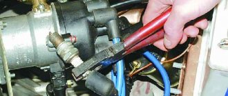
You need to remove the coil from its place by disconnecting the negative terminal of the Priora battery. Decorative plastic is removed from the motor. Then you need to press out the plastic clamp and disconnect the coil from the wiring, after which the fastening bolt is unscrewed with a 10mm wrench and the device is removed from the spark plug well.
Problems with coils can lead to sudden jerks in engine operation, speed surges, and cylinder failures. Therefore, if you have such symptoms, it is better to use the above information and replace the suspicious part before it completely fails. It also happens that the coil has not yet broken, but is already malfunctioning. This does not necessarily mean that a replacement is needed; some repairs will do, or rather cleaning of water condensation and dirt.
Sometimes coils fail when the spark plug gap is incorrect. Checking the performance of the coil on a Priora car can be easily done by turning the crankshaft. To do this, you need to relieve the pressure in the fuel system and remove the fuel pump fuse. Then we remove the coil, insert a spark plug into its rubber tip, and connect the wires to the coil itself.
You can check the coil power circuit. You need to take the multitester mentioned above and connect its probes to its terminals. If you turn on the ignition at this moment, the tester should show a voltage equal to that at the battery terminals. Otherwise, it is necessary to check the circuits for opens and shorts. If the power and control circuits are working properly, but when checking there is no spark on the working spark plug inserted into the tip, then the coil is faulty and will have to be replaced.
Design and principle of operation
So, starting the engine begins with turning the key in the ignition switch. At the same time, current must flow to the spark plugs, they give a spark to the fuel-air mixture, which is pumped up by the pump, the starter begins to rotate, causing the crankshaft to start moving. But the battery operates with low voltage electrical current.
Each coil is a small transformer. Two levels of winding are hidden under the housing of the element of the VAZ-2170 Priora ignition system. Its wires are low-voltage and high-voltage. The first ones receive current from the battery, the second ones transmit it to the spark plugs. When the current is converted, it is transferred to the spark plugs. The ECU “manages” this process, correctly distributing the force between the spark plugs.
As for how many ignition coils are in the Priora, there are 4 of them - one for each cylinder. Their work does not mix or overlap in any way. Each of them has “its own scope of work.”
IKZ device
The Priora coil consists of a primary and secondary winding, between which a core is placed. To contact the spark plug, a spring is used, which is placed in a rubber tip. The IKZ also has a metal screen that protects the coil from high temperatures, because IKZ is installed in the well of the cylinder head, then the temperature conditions there are simply enormous.
The primary winding is wound from thin copper wire with a number of turns of 10,000-15,000.
The secondary winding of the coil consists of 100-150 turns of thick copper wire.
The connection between the coils is electromagnetic.
Manufacturers and prices of analogues - which ignition coils are better for the Priora
No one, not even AvtoVAZ, promises that the analogue will work as long as the standard model. There are a sufficient number of options on the market. It will take quite a long time to determine which is better. The following components are suitable for Priora 16cl:
- SOATE (manufactured in Stary Oskol) (article 2112-3705010-12), price – 1,200 rubles.
- MZATE-2 (article 59.3705), price - 1,000 rubles.
- Baker Priora 2112-3705010-10 – 1100 rubles.
- Fenox IC16085 (STK) – 1,300 rubles.
Visual inspection of the IKZ
Remove the ignition coils from the engine using a 10mm or Torx E8 socket wrench (depending on the powertrain model). Carefully inspect the removed coils. There should be no cracks, damage to the rubber cap, melting or leakage of plastic. The spring located inside the coil must be in the correct position.
Performance check: how to check ignition coils on a Priora
Before you start replacing the ignition coils, you definitely need to check them and inspect them. Cracks, chips, and other damage to its body are unacceptable. If you see that the plastic is damaged, it means the part has overheated and cannot be used further.
The answer to the question of how to check an element of the 16-valve Priora ignition system is not limited to inspection. First you need to swap them and see if there are interruptions in the other cylinder. If there are interruptions, the problem is in the coil. There are several ways to use devices. To work you need:
- Secure the car in place and turn off the engine.
- Remove the negative from the battery.
- Disconnect the part from the motor, and then connect a fully functional spark plug to it.
- Turn off the fuel pump.
- Use protective equipment against electric shock, this is a must!
- Turn on the ignition and crank the starter. The spark plug should spark during normal operation.
- Sometimes repair of the Priora ignition coil begins after receiving data from the ECU. The codes start with 0301 and end with 0304, indicating each cylinder accordingly. However, the problem is displayed in the coil-plug module, so the culprit will have to be found out separately.
Now we check the ignition system element on the Priora with a multimeter. For this and further work with components, models AZ-1 or MD-1 are suitable. For this:
- Remove the part to be examined from under the hood.
- Set the measurement switch to the “200 Ohm” position, connect the probes. The display should show “0” or values close to it.
- Using probes, the external winding is checked. Pinout – 1.3. The display should show exactly 0.08 Ohm. The error is the number that the display showed during calibration; it must be subtracted. If nothing is shown, check that the probes are accurately touching the winding. If there is contact, but there is no result, the winding is broken and needs to be replaced.
- Set the multimeter to 2 MΩ measurement limit to test the high voltage winding. Connect the black probe to the terminal of the second connector, and the red probe to the terminal of the coil. The indicator should be 342 kOhm - but only for a cold part. It should be cooled before testing. This also requires checking the exact contact with the probe.
Remember that the winding of this spare part does not change, but the tip can be easily changed. Most often, repairs are limited to routine replacement - in order to be completely sure of the tightness of the part.
Checking the ignition coil
There are two reliable ways to check IKZ: visual inspection and checking with a multimeter.
It should be noted that the IKZ check is similar for all Lada cars with a 16-valve engine, i.e. the check on cars such as LADA Vesta and X-ray will be the same.
In order to check the ignition coil, it must be removed from the car.
Removing IKZ:
- Disconnect the negative terminal from the battery.
- Remove the decorative plastic trim.
- We unscrew the coil we need with a “10” or Torx E8 head.
- Remove the coil plug and remove it.
Visual inspection
After the coil is removed, it must be carefully inspected. The rubber tip should not have tears or cracks. The plastic part must not be melted or cracked. The contact spring must be in the correct shape without oxidation or rust.
Crack in the coil
Cracks in the coils or tears in the rubber cap will direct the spark to the engine body, therefore, no current will be supplied to the spark plug, which will lead to misfires.
Cracks in the rubber band
If such visual faults are detected, the coil must be replaced.
Checking with a multimeter
Testing with a multimeter is divided into two stages. Checking the resistance of the IKZ itself and checking the control voltage of the IKZ (checking the voltage on the IKZ power supply block).
Let's start by checking the voltage at the IKZ power supply.
To do this, set the switch on the multimiter to constant voltage.
Turn on the car ignition
On the block in connector number 3 we take a measurement (we connect one multimeter probe to the motor body and the other to pin number 3) the voltage should be at least 12 volts. If the voltage is less, this means that the battery is discharged or the ECU controller is faulty.
Checking the IKZ resistance
In order to check the resistance of the IKZ, you need to use a multimeter. It should be noted that resistance measurements must be carried out on a cold engine, because The resistance of the coil windings strongly depends on its temperature.
To check the resistance, it is necessary to check two windings, the secondary and the primary.
Checking the primary winding of the IKZ
When checking the primary winding of the IKZ, it is necessary to set the resistance readings on the multimeter, namely 200 Ohms. Since the resistance readings on the primary winding are not large, and the error of the device is possible, you first need to find out the error of the multimeter. In order to find out the error, you need to close the probes together, the value that will be reflected on the multimeter screen will be the error.
In this case, the instrument error is 0.7 Ohm
Next, we connect the multimeter probes to contacts 1 and 3 (the outermost contacts of the IKZ) and obtain resistance readings. From these readings we subtract the multimeter error and get the true value of the resistance of the primary winding.
Ideally, the resistance of the primary winding should be about 1 Ohm, or better yet 0.
In this example, the reading is 1.1 Ohm without taking into account the error; from 1.1 Ohm we subtract 0.7 Ohm to get 0.4 Ohm. Verdict: the primary winding of this IKZ is in working condition.
Checking the secondary winding of the IKZ
In order to check the secondary winding of the IKZ, set the multimeter to 2000 kOhm.
We connect the red multimeter probe to the spring, and the black one to the middle contact on the IKZ (pin 2). We look at the readings of the device; on a working coil, the resistance of the secondary winding should be in the range of 300-400 kOhm.
As we see, the readings of the secondary winding are also within the normal range. It follows that this IKZ is working.
If the readings are too high, you can try removing the rubber cap and spring from the coil and cleaning the contact patch, then measure the resistance directly again without the spring. If the resistance reading still does not decrease, you should think about replacing the ICP.
The easiest method to detect a faulty ignition coil, without any devices or instruments. This is a reversal of the IKZ.
Removing and installing a coil on a Priora
To change the ignition system element in a 16 valve engine, follow these steps:
- Park the car level, securing it with the hand brake.
- Raise the hood and remove the negative from the battery.
- Undress the motor by removing its plastic protective casing.
- Find the spare part you need, and then the wire block connected to it.
- Squeeze the wire block clamp and turn off the power.
- Using the 10th key, unscrew the bolt that secures the part to the metal.
- Carefully remove the spool, trying to move it vertically. It would be a shame to damage the wiring at the very last moment.
- Remove the faulty part and replace it with a new one. Tighten the fastening bolt, connect the wire block and place the negative on the battery. Check functionality.
Ignition system of VAZ 2170 Priora
- Repair manuals
- Repair manual for VAZ 2170 (Priora) 2004+.
- Ignition system
Repairing a car yourself remains a rather difficult task, especially if you consider the ignition system of the VAZ 2170 Priora. Today you can find a large number of various recommendations that tell you how to solve some problems during the operation of a particular car unit, but the bulk of such resources are based only on generalized information , without delving into the subtleties and details, on which not only the duration of operation, but also its effectiveness often depends.
Our information portal offers you full support in this matter. The presented repair manuals and detailed descriptions of the units are available online 24 hours a day. If necessary, you can get a more convenient, handy version by simply downloading it from the page. A detailed description of the parameters and what the ignition system of the VAZ 2170 Priora consists of, important aspects for correct and reliable installation will help to significantly reduce the risk of unexpected car breakdowns. Information provided about all components online allows you to quickly and effectively monitor any defects and defects, even before they appear during operation.
Most of the data presented on the site is taken from the instructions, but at the same time, it is much better structured and disclosed in detail to the user. Using them as an application database, you can always install and repair cars with your own hands, no less efficiently than in a car service center. But to do this you need to have a certain amount of knowledge, which can be replenished on our website.
Having studied all the necessary features of the unit, the car owner will gain invaluable experience in handling not only original, but also contract options. It's no secret that the original will in 100% of cases meet the assigned tasks as part of the car, but there is always a risk of manufacturing defects, which can be easily determined using our recommendations.
A good contract spare part is almost as good in quality and reliability as the original models. However, in most cases, important nuances remain during installation and operation, knowledge of which will help maintain the performance of the analogue at the proper level. Most sections of the site are devoted to these and many other important points.
10.8.1 Ignition system Removing and installing ignition coils The ignition system does not use a traditional distributor... ...individual ignition coils are used here. The ignition system has no moving parts, so it requires no maintenance or adjustments. In the system for…
10.8.2 Removing and installing ignition coils You will need a “10” socket. 1. Disconnect the wire from the negative terminal of the battery. 2. Remove the decorative casing from the engine (see “Removing and installing the decorative engine casing”). 3. Press out the plastic clamp... 4. ...and disconnect from you...
↓ Comments ↓
1. Car structure
1.0 Car structure 1.1 General information about the car 1.2 Passport data 1.3 Car keys 1.4. Controls 1.5. Heating and ventilation of the cabin 1.6 Ensuring a comfortable air temperature in the cabin 1.7. Doors 1.8. Passive safety equipment on the car 1.9. Seats
2. Recommendations for use
2.0 Recommendations for use 2.1. Safety rules and recommendations 2.2 Running in the car 2.3 Operating the car during the warranty period 2.4. Preparing the car for departure
3. Problems along the way
3.0 Malfunctions along the way 3.1. The engine does not start 3.2 Malfunctions of the fuel injection system 3.3 Idle speed has disappeared 3.4. Interruptions in the operation of the 3.5 engine. The car moves jerkily 3.6 The car accelerates poorly 3.7 The engine stalled while driving 3.8. Oil pressure dropped to 3.9. Engine overheating 3.10. The battery does not recharge 3.13. Knocks in the engine 3.16. Wheel puncture
4. Maintenance
4.0 Maintenance 4.1. General provisions 4.2. Inspection work 4.3. Lubrication and filling works 4.4. Diagnostic work 4.5. Repair and adjustment work
5. Engine
5.0 Engine 5.1 Design features 5.2 Possible engine malfunctions, their causes and solutions 5.3 Useful tips 5.4 Checking compression in the cylinders 5.5 Removing and installing the decorative engine casing 5.6 Removing and installing the engine splash guard 5.7 Installing the piston of the first cylinder to the TDC position of the compression stroke 5.8 Replacing the drive belt gas distribution mechanism and tension roller 5.9 Replacing the power unit supports 5.11. Replacing engine seals 5.13. Engine cylinder head 5.15. Engine repair 5.16. Lubrication system 5.17. Cooling system 5.18. Power supply system 5.19. Design Features
6. Transmission
6.0 Transmission 6.1. Clutch 6.2. Gearbox 6.3. Front wheel drives
7. Chassis
7.0 Chassis 7.1. Front suspension 7.2. Rear suspension
8. Steering
8.0 Steering 8.1 Design features 8.2 Possible steering malfunctions, their causes and solutions 8.3. Steering column 8.4. Steering linkage 8.5. Steering gear
9. Brake system
9.0 Brake system 9.1 Design features 9.2 Possible malfunctions of the brake system, their causes and solutions 9.3 Bleeding the brake system hydraulic drive 9.4 Removing and installing the vacuum brake booster 9.5 Replacing the brake pedal axle bushings 9.6. Main brake cylinder 9.7. Front wheel brakes 9.8. Braking mechanisms of the rear wheels 9.9. Pressure regulator 9.10. Brake hoses and tubes 9.11. Parking brake
10. Electrical equipment
10.0 Electrical equipment 10.1 Design features 10.2. Battery 10.3. Mounting block (relays and fuses) 10.4. Generator 10.5. Starter 10.6. Ignition switch (lock) 10.7. Electronic engine control system (ECM) 10.8. Ignition system 10.9. Lighting, light and sound signaling 10.10. Windshield cleaner 10.11. Washer reservoir 10.12. Electric fan of the engine cooling system 10.13. Electric motor of the heating and ventilation system fan 10.15. Cigarette lighter 10.16. Instrument cluster 10.18. Electronic anti-theft remote control system 10.19. Immobilizer 10.21. Replacing sensors and switches
11. Body
11.0 Body 11.1 Design features 11.2 Possible body malfunctions, their causes and solutions 11.3 Removing and installing windshield frame lining 11.4 Removing and installing soundproofing upholstery in the engine compartment 11.5. Removing and installing bumpers 11.6 Removing and installing the fender liner and protective wing cover 11.7 Removing and installing the front fender 11.8 Removing and installing decorative sill trims 11.9. Hood 11.10. Trunk lid 11.11. Doors 11.12. Seats 11.13. Seat belts 11.14. Rear view mirrors 11.15. Interior fittings 11.16. Instrument panel 11.17. Heater 11.20. Body care
12. Applications
12.0 Appendix 12.1 Appendix 1. Tightening torques of threaded connections, Nm 12.2 Appendix 2. Fuels, lubricants and operating fluids 12.3 Appendix 3. Nominal filling volumes 12.4 Appendix 4. Basic data for adjustments and monitoring 12.5 Appendix 5. Spark plugs used on vehicles 12.6 Appendix 6. Lamps used on a car 12.7 Appendix 7. What you need to have in a car 12.8 Appendix 8. Tools used when repairing a car
13. Electrical diagrams
13.0 Electrical Diagrams 13.1 Diagram 1. Instrument Panel Harness Connections 13.2 Diagram 2. Vehicle Front Wire Harness Connections 13.3 Diagram 3. Engine Electronic Control System (ECM) Harness Connections 13.4 Diagram 4. Vehicle Rear Wire Harness Connections 13.5 Diagram 5. Light Harness Connections license plate light 13.6 Diagram 6. Left front door wiring harness connections 13.7 Diagram 7. Right front door wiring harness connections 13.8 Diagram 8. Rear door wiring harness connections
Pinout of the lighting control unit on Priora
This switching and control combined module has several functions and is used to turn on/off parking lights, headlights, select the desired light switching mode, turn on/off fog lights, adjust the brightness of the backlight combination, control the headlight range control, on/off and control light inside the cabin and instrument lighting. The module is connected to the vehicle’s on-board network via chip No. 1118-3724500.
The standard terminal pinout on a VAZ 2170 is as follows:
| G, 56b | To the gear motor for adjusting headlights |
| 58b | Output to backlight sources |
| 31 | Weight |
| Xz | +12 volts (from terminal 15 of the ignition switch) |
| 56 | To the relay for switching high and low headlights |
| 1,3 | From rear and front fog lights |
| 2,4 | To the rear and front fog lamp relays |
| 58 | To the size lamps |
| 30 | +12 V from terminal No. 30 of the ignition switch |
Pinout and diagram of the VAZ ignition coil
Pinout of ignition coil modules for various car models of the VAZ family:
Ignition VAZ 2101
1 – generator; 2 – ignition switch; 3 – ignition distributor; 4 – breaker cam; 5 – spark plugs; 6 – ignition coil; 7 – battery.
Ignition VAZ 2106
1 – ignition switch; 2 – fuse and relay block; 3 – EPHH control unit; 4 – generator; 5 – solenoid valve; 6 – microswitch; 7 – spark plugs; 8 – ignition distributor; 9 – ignition coil; 10 – battery.
Ignition VAZ 2108, 2109
Ignition VAZ 2110
Ignition VAZ 2111
Ignition VAZ 2112
Ignition VAZ 2114
Diagram of a non-contact ignition system: 1 – non-contact sensor; 2 – ignition distributor sensor; 3 – spark plugs; 4 – switch; 5 – ignition coil; 6 – mounting block; 7 – ignition relay; 8 – ignition switch.
Tip repair
A cracked ignition coil tip is a common problem. However, you can return the coil to working condition by making repairs on your own, provided that the coil itself has not burned out. This will require a degreasing wipe, a silicone ignition coil O-ring (new), a new tip and silicone sealant. The whole procedure will take a couple of minutes.
We wait a while for the sealant to fix the part. We wipe the entire coil with a degreasing cloth, which is now brought back to life. Pay attention to the contact spring; it should move freely in the tip cavity. The necessary parts for the job can be purchased at car markets and online stores. Good luck!
With numerous, and sometimes even minor misfires, the engine may operate unstably, floating speeds will appear, the car may jerk while driving, etc. To determine which cylinder is faulty, it is necessary to alternately remove the coil power plug from each of them, or rather, disconnect it for a while.
If, if one of the cylinders is disconnected, interruptions in operation are still present, then this is where the reason lies. Often, it is the ignition coil of one of the cylinders that leads to the consequences described above. And to replace it, you will need the following tool:
- 10 mm head
- Extension
- Ratchet or small wrench