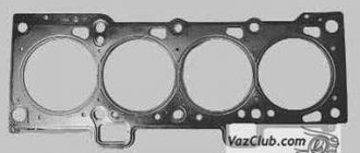
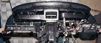
The motor control system includes a wide range of different elements, each of which plays its own important role.
In some situations, high voltage disappears on several or even one cylinder. The reason for this may be the ignition module on the VAZ 2110, or rather its malfunction.
It should be noted that replacing the ignition module of the VAZ 2110 may not be necessary. First try to repair it, diagnose and fix the problem.
What determines the performance of the coil?
The classic ignition coil or “bobbin”, as it is also popularly called, is essentially a low-voltage voltage converter from the battery and generator to high-voltage, which is then supplied to the spark plugs. That is, this is a miniature electrical transformer.
The ignition coil is a kind of mini electric transformer
The traditional coil, used on carburetor models of vehicles, consists of two windings. The primary winding receives low voltage pulses, for example 12 Volts. As a rule, this is a small number of turns (up to 150) of thick insulated copper wire. The “primary” has 2 terminals on the coil cover. There are much more turns in the secondary winding - up to 30 thousand, but the wire used is much thinner. One end of the “secondary” goes to the “minus” of the primary winding, the other to the central terminal of the coil. In the center of the windings there is a core that enhances the magnetic field. The coil body is insulated, and its cavities are filled with special oil for transformers.
The fundamental characteristic that indicates the serviceability of almost any coil is the resistance of the windings.
How to check the ignition coil with a tester on a VAZ 2106, as well as VAZ 2109 and VAZ 2110 (carburetor)
On old VAZs it is not difficult to find a coil. It is located in a freely accessible area, under the hood. To check, you will need a regular multitester, which can be purchased for a small amount in many stores.
Video tutorial on measuring ignition coil resistance
The procedure is as follows:
- Disconnect the negative voltage on the battery. Disconnect the ignition coil wires, loosen the brackets. Clean the reel body. If obvious damage, cracks, etc. were discovered, it is better to immediately replace the device with a new one, since such a coil cannot be used.
- On the tester, turn on the ohmmeter mode. To check the “primary”, install probes or clamps on the side terminals located on the coil body. The tester display will show about 3.07-3.5 Ohm (original coil 2106 for a contact ignition system) or 0.45 ± 0.05 Ohm (coil 27.3705 for a contactless ignition system). For VAZ 2108, 2109 and 2110 - 0.43±0.04 (coil 3122.3705) and 0.42±0.05 Ohm (coil 8352.12). If the “primary” is broken or burned out, the resistance indicators will most likely tend to infinity.
- "Secondary" requires a similar check. But now the first probe goes to the side terminal, and the second to the central terminal. In addition, the indicators will be calculated in thousands of ohms. So, in accordance with the factory figures for the VAZ 2106 it should be 5400-9200 Ohms, for 2109 and 2110 - 0.40 kOhm (coil 3122.3705) or 1.00 kOhm (coil 8352.12).
- Also check the insulation resistance to ground. To do this, install one probe on the coil body, the second on each of the terminals in turn. The tester should show at least 50 mOhm.
The ignition coil cannot be repaired
Strong deviations from the normal range are a reason to replace the coil with a new one. It should be noted that this element of the ignition system cannot be repaired.
We check the functionality of the ignition modules: injector 8 16 valves
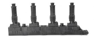
The ignition systems on carburetor and injection Ladas are very different. Thus, the “ten” was first equipped with a classic housing ignition coil, like the 2109. But then, with the start of installation of 8-valve injection engines under the hood, it became necessary to replace the old “bobbin” with a more modern ignition module. This element contains a two-channel switch and 2 coils at once, which provide a spark for two pairs of spark plugs. With the advent of the era of 16-valve engines, individual ignition coils began to be installed on Ladas - one for each spark plug. According to the rules, the ignition module must be checked on a special stand. But, as in the case of a classic coil, there is a chance to achieve the truth with the help of a tester.
A little about prices
We have already noted which switch and transistor are used when repairing the ignition module of a dozen. The first costs about 3 dollars, and for the second you will have to pay about 6 dollars.
Some craftsmen use a domestic analogue of the transistor - model KT848A . Of course, it costs less. But its problem is its lower quality and larger size, which somewhat complicates the repair process.
How to check the ignition module on a VAZ 2110 and VAZ 2114
To ensure that the ignition module on an 8-valve injection valve is working properly, you need to use a multitester in ohmmeter mode. The resistance between paired terminals should be measured.
That is, first measure the resistance of the “secondaries” between the terminals on cylinders 1 and 4, then on cylinders 2 and 3. Exact numbers can be found in the operating manuals for specific motors, but this information is not of great importance. The indicators simply should not differ from each other; an amplitude of ±100 Ohms is allowed. If the resistance in the pairs is different, the module must be replaced.
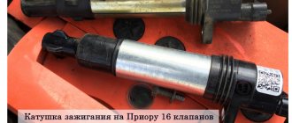
We check the serviceability of the ignition coils on a Priora with a multimeter
Unlike conventional 8-valve engines, which use an ignition module, more modern 16-valve power units come with 4 individual coils. German coils manufactured by Bosch are installed on the conveyor. Accordingly, professional equipment is provided to “treat” such parts. To do this you will need to shell out about $300, which is not cheap. However, in practice, cheap self-diagnosis is also possible.
Recommendation: before starting work with a multimeter (tester), check its accuracy. To do this, set the resistance to 200 Ohms and connect the probes to each other. Ideally, the display should show only zeros.
A car with a charged battery may not start due to a faulty ignition coil.
If not, just remember or write down this figure so that you can then subtract it from the measurement results as an error.
- Remove all coils from their seats and clean them of dirt. Check the coils for damage to the rubber elements. Nothing like this should happen - otherwise it should be replaced immediately.
- “Ring” the primary winding. To do this, connect the tester probes to pins 1 and 3 of the connector (outermost pins). Polarity doesn't matter. The resistance reading should be around 0.5 ohms. If there is a winding break, the tester will show a very large number, close to infinity.
- To measure the secondary resistance, switch the ohmmeter to the 2000 kOhm (2 mOhm) position. In this case, polarity is important: connect the red wire to the spring inside the cap, install the probe of the black wire on pin 2 (in the middle of the connector). The resistance should be about 342 kOhm.
Dear drivers, one of the reasons for poor engine starting is a burnout in the ECU of the power key gb10nb37lz.
But for some reason, many car owners immediately think that their Crankshaft Position Sensor has failed, I once had this problem. But this was also due to the fact that the wire from the sensor lay on ground and when the engine heated up, the braid melted and a short circuit occurred. In my blog: www.drive2.ru/l/6251079/
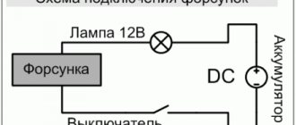
And so, our ignition diagram:
1 – battery 2 – ignition switch 3 – ignition relay 4 – spark plugs 5 – ignition module 6 – controller 7 – crankshaft position sensor 8 – master disk A – matching device
When the car does not start, most people immediately blame the crankshaft position sensor. Changing it they realize that it didn’t help. When checking the block, the wire does not give any result. The next steps are to install a new module, or this also does not give the computer anything. The car still won't start.
Everything is simple: the crankshaft sensor just has its own resistance, like the ignition module, by ringing it you can understand whether they are in good condition. Also don’t forget to check the fuse and main relay. Next, we check the spark plugs and armor wires to see if the retractor on the starter works (just put your hand on it, and if it doesn’t hit when starting, it means it’s working). During this check, you can understand what is wrong.
Checking the Crankshaft Position Sensor:
2. We quickly move the screwdriver blade close to the end of the sensor, while we observe voltage surges on the voltmeter.
Conclusion: The sensor is working.
Checking the DPKV circuit: With the ignition off, disconnect the engine management system wiring harness block from the crankshaft position sensor. We connect the tester probes to terminal “B” of the wiring harness block and engine ground.
Connection diagrams for a magnetic starter with a 220 V coil
Before we move on to the diagrams, let’s figure out what and how these devices can be connected. Most often, two buttons are required - “start” and “stop”. They can be made in separate housings, or they can be a single housing. This is the so-called push-button post.
Everything is clear with individual buttons - they have two contacts. One receives power, the other leaves it. There are two groups of contacts in the post - two for each button: two for start, two for stop, each group on its own side. There is also usually a ground terminal. Nothing complicated either.
Connecting a starter with a 220 V coil to the network
Actually, there are many options for connecting contactors; we will describe a few. The diagram for connecting a magnetic starter to a single-phase network is simpler, so let's start with it - it will be easier to understand further.
Power, in this case 220 V, is supplied to the coil terminals, which are designated A1 and A2. Both of these contacts are located at the top of the case (see photo).
If you connect a cord with a plug to these contacts (as in the photo), the device will be in operation after the plug is inserted into the socket. In this case, any voltage can be applied to the power contacts L1, L2, L3, and it can be removed when the starter is triggered from contacts T1, T2 and T3, respectively. For example, a constant voltage from a battery can be supplied to the inputs L1 and L2, which will power some device that will need to be connected to the outputs T1 and T2.
When connecting single-phase power to the coil, it does not matter which output is supplied with zero and which with phase. You can switch the wires
Even most often, the phase is supplied to A2, since for convenience this contact is located on the bottom side of the housing. And in some cases it is more convenient to use it and connect the “zero” to A1.
But, as you understand, this scheme for connecting a magnetic starter is not particularly convenient - you can also supply conductors directly from the power source by building in a regular switch. But there are much more interesting options. For example, you can supply power to the coil through a time relay or light sensor, and connect a power line to the contacts. In this case, the phase is connected to contact L1, and zero can be taken by connecting to the corresponding coil output connector (in the photo above it is A2).
Diagram with start and stop buttons
Magnetic starters are most often installed to turn on an electric motor. It is more convenient to work in this mode if there are “start” and “stop” buttons. They are connected in series to the phase supply circuit to the output of the magnetic coil. In this case, the diagram looks like the figure below
note that
But with this method of switching on, the starter will operate only as long as the “start” button is held down, and this is not what is required for long-term operation of the engine. Therefore, a so-called self-catching circuit is added to the circuit. It is implemented using auxiliary contacts on the starter NO 13 and NO 14, which are connected in parallel with the start button.
In this case, after the START button returns to its original state, power continues to flow through these closed contacts, since the magnet has already been attracted. And power is supplied until the circuit is broken by pressing the “stop” key or by triggering a thermal relay, if there is one in the circuit.
Power for the motor or any other load (phase from 220 V) is supplied to any of the contacts marked with the letter L, and is removed from the contact marked T located underneath it.
It is shown in detail in what order it is better to connect the wires in the following video. The whole difference is that not two separate buttons are used, but a push-button post or push-button station. Instead of a voltmeter, you can connect a motor, pump, lighting, or any device that operates on a 220 V network.
Checking the ignition module of the injection VAZ 2110 8/16 valves
The top ten may have an eight-valve engine 2111, with a volume of one and a half liters, or an engine 21114, with a volume of 1.6 liters. The difference between them is in the ignition modules.
The module for a one and a half liter engine has the article number 2112-3705010, and the module with a volume of one thousand six hundred cubic meters has the article number 2111-3705010. They also differ in price. If the cost of the first ranges from one and a half thousand rubles to 2100, then the cost of the second is cheaper by about five hundred rubles.
Which one should you choose? The most reliable ones are produced in the city of Stary Oskol.
Module structure
It consists of two ignition coils and two high-voltage switch switches. The coils are designed to create high-voltage pulses.
In essence, it is a simple transformer that has two windings: a primary winding, with an induction voltage of approximately five hundred Volts, and a secondary winding, with an inductive voltage of at least twenty kiloVolts. Everything is placed in one housing with one connector for signal wires and four for high-voltage.
Schematic diagram of the VAZ 2110 module
The operation of the ignition module is based on the “idle spark principle”. The module is capable of distributing a spark in pairs: to the first and fourth, second and third cylinders when transmitting pulses from the electronic control unit.
Possible faults
You can ring the VAZ-2110 ignition module yourself.
The main task of the module is to supply current to the spark plugs. A high-quality spark is enough to ignite the working mixture. If there is no spark, then problems with the engine are inevitable in the form of a decrease in power, an increase in fuel consumption, dips during acceleration, the speed fluctuates, and the engine refuses to work during startup.
Symptoms and check
If one coil fails, two cylinders stop functioning. This is easy to notice, since the engine becomes heated at idle, starting is difficult, gasoline consumption increases sharply, and dynamics are lost.
We remove the connector from the VAZ 2110 module by slightly moving the latch and pulling the wire.
We check the voltage between pin 15 and the block ground.
Circuit for checking the primary windings
Secondary winding test circuit
Scheme for checking the module for short circuit
You need to make sure the spark plugs are working. They are unscrewed and the spark is checked separately on each of the spark plugs. A high-voltage wire is placed on the spark plug head. The spark plug is placed in such a way that the threaded part of the spark plug and the engine mass are in contact. If, when cranking the engine with the starter, the spark is very weak or absent altogether, then it needs to be replaced. If there is no result, you need to check the high-voltage wires. This excludes spark plugs, caps and high-voltage wires from the list of faults. This means it’s time to move on to checking the ignition module. How to do this?
First of all, the body is carefully inspected, the surface of which must be intact. If chips, cracks or burns are detected, then the module must definitely be replaced.
If spark instability is noticed only on the first and fourth, or second and third cylinders, then the conclusion arises that some coil is damaged.
Even if this is the case, due diligence needs to be done.
Checking the VAZ-2110 ignition module with a multimeter 8 valves is as follows:
- The connector with signal wires is disconnected from the module.
- It is then removed from the module. The latch must be moved to the side and pulled by the wire.
- The ignition is turned on to check the voltage at the terminal of the central block of control wires. If there is no voltage when the battery is charged, or if the value is less than the nominal value, which is twelve volts, it is concluded that the electronic control unit is faulty.
- The high-voltage wires are removed, and it is necessary to unscrew and remove the module mounting bots.
- The resistance on the primary windings of the coils is checked. The multimeter is set to resistance measurement mode. Using the device, readings are taken from the rightmost and central terminals, then the leftmost and central ones are checked. The nominal resistance should be about 0.5 ohms.
- The primary windings are checked. The resistance in the secondary windings is measured between the terminals of the first and fourth, second and third high-voltage wires. Nominal resistance 5.4 kiloohms. If a discrepancy is found, it means that the coil is not operating correctly.
- The module is checked for a short circuit. One of the tester probes is installed on the central terminal, the other on the metal body. If there is no indication of a short circuit, a conclusion is drawn that the housing of one of the coils is short-circuited.
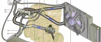
Contactless engine ignition system 2110
Diagram of a contactless ignition system.
The contactless ignition system consists of an ignition distribution sensor 2, a switch 4, an ignition coil 1, spark plugs 3, an ignition switch 5 and high voltage wires. The power supply circuit for the primary winding of the ignition coil is interrupted by an electronic switch. Control pulses are supplied to the switch from a contactless sensor (Hall sensor) located in the ignition distributor sensor.
Ignition distributor sensor - type 40.3706 or 40.3706–01, four-spark, unshielded, with vacuum and centrifugal ignition timing regulators, with a built-in microelectronic control pulse sensor (Hall sensor).
Switch – type 3620.3734, or 76.3734, or RT1903, or PZE4022. It converts the sensor control pulses into current pulses in the primary winding of the ignition coil.
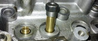
Ignition coil - type 3122.3705 with a closed magnetic circuit, dry or type 8352.12 - oil-filled, sealed with an open magnetic circuit. Spark plugs - type A17DVR, or A17DVRM, or A17DVRM1, or FE65PR, or FE65CPR with noise suppression resistors.
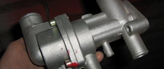
Ignition switch - type 2110–3704005 or KZ–881 with an anti-theft locking device, with a lock against re-starting the starter without first turning off the ignition and with an illuminated socket.
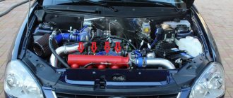
The ignition system of the 2110 engine is an injector.
The VAZ 2110 injection engine control system is a group of complex electronic and mechanical devices that require certain knowledge and approaches to repair. It consists of a set of sensors, actuators and a central control unit - the controller.
Location of elements of the injection engine control system 2111
- mass air flow sensor;
- coolant temperature sensor;
- knock sensor;
- adsorber for gasoline vapor recovery system;
- crankshaft position sensor;
- throttle pipe (it contains a throttle position sensor and an idle speed regulator);
- speed sensor (located on the gearbox);
All injector actuators are controlled by a central unit—the controller. The information received from the sensors is read by the controller and, based on them and the control program embedded in it, signals are sent to various actuators. The engine control unit may vary in modification and firmware version.
There are two distributed injection systems:
- With feedback.
- No feedback.
A system with feedback differs from a system without it by the presence of a neutralizer and an oxygen sensor. The DC provides feedback and participates in calculations of the optimal gasoline-air ratio of the fuel-air mixture, ensuring optimal operation of the converter. Thanks to this, higher levels of toxicity standards and emissions of harmful components into the atmosphere are achieved. Also in this system there is a system for collecting gasoline vapors - an adsorber.
The above devices are not installed in the open-loop injection system. To ensure toxicity standards, there is an adjustment of CO in the exhaust gases using a CO potentiometer.
The modified 2112 engine uses a sequential distributed fuel injection system - phased injection. It has another device - a phase sensor installed near the camshaft. It determines the moment of the end of the compression stroke in the 1st cylinder, and fuel is supplied by injectors to the cylinders in the sequence corresponding to the ignition order in them: 1c - 3c - 4c - 2c.