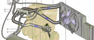
On the VAZ 10th family, which includes the VAZ 2110-2112 models, the designers used an electronically controlled interior heating system, thanks to which the temperature set by the driver is maintained automatically.
On the VAZ-2110, instead of a manual heater control mechanism with a cable drive of the main elements - the coolant shut-off valve and dampers, an automatic heater control system (AHC) controller with a temperature sensor and a gearmotor that regulates the position of the dampers are used.
In such a stove, the valve for shutting off the antifreeze supply is no longer used, and the adjustment of the heater operating mode - “heating” or “ventilation” - is carried out by a central damper, which directs the air flow through the radiator or bypassing it.
How malfunctions manifest themselves
The automatic temperature maintenance system used on the VAZ-2110 is more convenient in terms of control, since the automatic control system does everything independently, but is less reliable than a mechanical cable drive. Moreover, problems are caused by the electronic and electrical components of the stove - the controller, temperature sensor and micromotor gearbox, the central damper, which regulates the air supply to the cabin from the outside.
Problems with the operation of the VAZ-2110 heater related to the damper:
- lack of temperature control (only hot or cold air comes from the stove) regardless of the position of the handle on the controller;
- insufficient air heating (even when setting the handle to the maximum temperature);
- squeaks, knocks and extraneous noises after setting the temperature.
The cause of such problems is the central damper of the VAZ-2110 stove, which is adjusted by the controller through a gearbox. The design of the stove includes another damper - air distribution into zones. It is controlled using a handle mounted on the central air supply deflector into the cabin, so malfunctions with this part are rare.
Trouble-shooting
Checking the cabin air temperature sensor
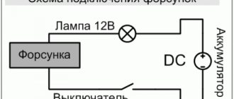
You can check the serviceability yourself; special skills are not required. Carefully remove the sensor from its original place. We find the contacts on the back side. Using a multimeter, apply a voltage of 1.2V. We set the regulators of the automatic heater control system to the “Min”, “Max” positions. The motor should not be activated.
The second method is to turn off the cabin air sensor. Check fan speed settings. The first speed (“A”) should be inactive.
Video: Heater VAZ 2110, 11, 12. Design and principle of operation.
Checking the proper operation of the automatic control system
The proper operation is checked with a multimeter. The voltage at the terminals of the pink and brown wires is measured, the ignition is activated. Smoothly turn the temperature regulator; the arrow on the multimeter display should show an increase in voltage.
On old-style heaters, at maximum voltage, the controller value remains unchanged. Take this into account so as not to make hasty conclusions about the malfunction of a particular unit.
The cause of controller malfunction may also be deformed dampers. To verify this and eliminate the breakdown, we disassemble the heater.
Prevention of the damper of the heating system of VAZ 2112
To be precise, two dampers are subject to inspection; this is the number of them present in the VAZ 2112. The cold air intake is regulated in the upper part. In the lower part, warm (hot) air is supplied to the car interior. Due to wear on the drive mechanism, the damper opens halfway or partially, the air flow is reduced, and the interior is not heated sufficiently.
Features of the design of the VAZ - 2110 stove damper
Note that VAZ-2110 of different years of manufacture uses heaters that differ in design:
1. Old-style stove damper
Old heaters use two central dampers, one of which blocks the flow of air into the cabin from the outside, and the second one redirects the air flow to the heater radiator or bypasses it. They are interconnected by drives and opened by a micromotor gearbox.
2. New sample
In the new type of stove there is only one central damper and it is connected by a drive to the gear motor directly, and not through a lever.
3. Under the “Euro” panel
Structurally, such a stove does not differ from the new type of heater, but in it the damper for distributing the air flow into zones is controlled by another micromotor gearbox.
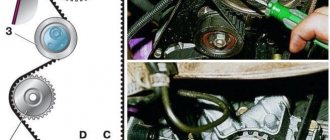
It is easy to visually distinguish the stoves by the location of the heater fan. In the old-style interior heater, the fan is located horizontally, while in the new model, it is positioned vertically. Their gearmotors are also different.
The device of the VAZ 2112 stove
Heater parts
- electro-pneumatic valve;
- front housing;
- water deflector;
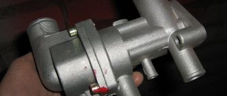
- control valve;
- back of the case;
- radiator;
- radiator casing;
- lid;
- resistor;
- Electrical engine.
Heater ducts and controls
- Rear heating ducts.
- Plastic lining of the tunnel.
- Foot heating channels.
- Ventilation nozzles of the central part.
- Side nozzles.
- Heated front doors.
- Mechanical heating lever.
- Distributor housing.
- Damper for heating feet, windshield.
- Heater.
It is important to know!!! Differences in the design of the old and new VAZ 2112 in the shape of the heater radiator, the SAUO controller, and the micro-gearbox. Conventionally divided before 2004 and after. When purchasing, be careful not to hand over unnecessary parts.
From the above it follows that the heating system of the VAZ 2112 operates separately. The VAZ 2112 stove pumps air at the required temperature into the cabin. The pipes supply flow to heat the windshield, passengers' feet, and rear row of seats. Deformation of the dampers and deflectors creates an obstacle to the air flow, so the stove does not blow well and requires diagnostics.
Causes of malfunctions
Depending on the design of the stove, the damper may cause a disruption in the efficient operation of the heater for the following reasons:
- deformation;
- wear of seals;
- deterioration or damage to control levers and rods;
- skew.
Deformation is a problem with old-style heaters. The first dampers of the VAZ-2110 stove were equipped with plastic elements that bent under the influence of temperature. Because of this, even when completely closed, cold air from outside leaks in and mixes with the heated air, and the efficiency of the stove decreases. Subsequently, the designers replaced the plastic flaps with aluminum ones and the problem with deformation disappeared.
To ensure tightness, the dampers have seals that reduce air leakage. Initially, foam rubber seals were used, which quickly wore out and became damaged. Later, foam rubber was replaced with rubber, but this only extended the service life of the seal; over time, the rubber ages, cracks and collapses.
On old-style stoves, rods and levers may break. On new heaters, there is another problem - wear on the edges of the square end of the gearbox, with which it is inserted into the groove made in the damper axis. As a result, the limit switch bypasses the groove, and the heater damper jams, although the gearmotor operates. The misalignment occurs due to the displacement of the damper axis in the mounting holes of the housing. Because of this, the damper warps and jams when opening.
We disassemble and repair the heater damper gearmotor of VAZ-2110, 2111 and 2112
to disassemble and repair the heater damper gearmotor of VAZ 2110, 2111 and 2112 with our own hands . It is known that not all modifications of the stove are suitable for the gearmotors discussed in this article. The materials were tested on a VAZ-2112 produced in 2005 and a VAZ-21113 produced in 2004. In our case, the car is equipped with a stove with an air filter but without recirculation, without air conditioning, without an automatic mode for adjusting the temperature of the stove. So far, only two models of damper gearmotors have been examined in detail. The examples are quite vivid and will probably answer the question of which one to choose, what is more reliable than metal or plastic and is it better if it costs more... The first example is a heater gear motor 2110 in a plastic case , removed from the car for the first time in 10 years and installed on the car by the manufacturer. It stopped working for an unknown reason. Let's open it! View from different sides
First of all, we remove the plastic adapter of the gearmotor from the shaft, the one that is inserted into the damper itself and transmits rotation to it. We do this boldly, pull and remove, there is no glue or stoppers, the shaft has longitudinal milling that practically eliminates incorrect installation during assembly, but more on that later.
Along the perimeter of the product body we find several latches of this type
Here, to open it you will need a pair of flat screwdrivers, wider and narrower. It's better to take old ones because you'll have to sharpen them sharper. Oddly enough, there are no grooves under the latches, they cannot be recessed by pressing them, there is nowhere for them to press, so we drive a small screwdriver between the latch tongue and the second half of the product body directly into the place where the tongue is held, not deep, just slightly raise the eye and the main thing is not to tear it off, just a little, this will be enough. We insert the second wide screwdriver next to the latch in the place where the housing halves connect, insert it and open the halves a little with a turning movement, while taking out the small screwdriver. So along the entire perimeter.
Further, carefully, small parts may fall out, it is important not to lose them. Then one half is removed completely, pulled up from the axis and we get this picture.
Three gears, remove them safely
On the second there remains an electric motor with a gear on the shaft
We pay attention to a few little things when removing the motor from the housing; at the end of the worm gear there is a segment designed for centering the shaft and preventing the pair of gears from disengaging. This is a separate small detail, it is important not to lose it. In the body there is a semicircular recess for this segment, i.e. Otherwise you won’t be able to insert it, just one side. We also pay attention to the locking screw in the motor housing to see if it is lost or unscrewed. The stopper prevents the motor itself from turning in the product body.
The motor is taken out, the gear and segment are removed from its shaft, there is no glue or stoppers. We see that the motor shaft also has a milling to transmit rotation to the gear.
Having examined all the removed plastic gears, we conclude whether it is necessary to look deeper for the cause of the failure, if all the gears and their teeth are intact, the axles are in place, the stoppers, etc., then we probably need to look deeper. Let's disassemble the motor. From the side where the wires are connected, two places where the motor parts are fixed are visible; using something at hand, we bend the housing in these places, thereby freeing the bottom plastic part.
Then everything is interesting again, the insides are easy to break. There is a permanent magnet inside, it holds the armature of the motor inside with a magnetic field, so you can’t pull on the plastic bottom, in addition, there’s a big risk of tearing off the brushes and then everything will turn to dust. Here's how we do it. The motor has a rather long shaft, take the motor in your hand and press your finger on this shaft, pushing it in
You can see in the photo that the bottom part is hanging in the air, it is the brushes that hold it, and the anchor hangs on the magnetic field and tends to its place. It is still impossible to pull off the bottom part, we press the shaft as much as possible with our finger and with the other hand, we grab the anchor with our fingers, only using the anchor we separate the parts of the motor. You shouldn't take hold of the windings either, they are easy to damage, there is enough steel there, you shouldn't take hold of it. If your fingers do not fit, you can push the shaft with something thin, such as a nail or an awl, the anchor will come out stronger, and there will be more space.
Two brushes are attached to the bottom part; when disconnecting the armature and the bottom part, use a screwdriver to carefully pull the brush by its holder, one and then the other. No sudden movements. There is a washer at the end of the anchor, which prevents you from simply pulling the bottom part off the anchor; with this washer, the risk of tearing off the brushes is very high. This washer does not come off on its own and there is no point in trying, it is of no use.
We see three windings at the armature, inspect them, check with a tester on the commutator to see if these windings are intact. We inspect the bottom part, the brush holders, and the brushes themselves to see if there are any critical wear marks, melting, or soot. In this case, traces of soot and soot were found on the commutator, and in a certain position, because of this, there was no contact of the brush with the commutator.
Assembly. First the motor itself. Not forgetting about the washer on the anchor, moving one brush apart at a time, we insert the anchor into place. The bushing in the bottom part may turn sideways during disassembly, this is normal, it is self-centering, we place it in advance with the hole up so that the armature shaft fits into it during assembly. Here is the intermediate result, brushes on the washer...
We insert the shaft completely, make sure that everything went well, the brushes are intact and in place, touching the commutator.
Just like when disassembling, we take the anchor by the iron, insert it all into the case, don’t forget about the magnet, hold it tightly. When assembling, we clamp the hole for the long shaft with our finger so that the shaft does not slip under the influence of the magnet, release the finger and at the same time insert the bottom part until it stops. We check the ease of rotation of the shaft from the force of the fingers, bend the clamps of the bottom part. You can take a 9-volt battery of the Krona type and connect it to the terminals directly on the motor to check whether the motor is working. We take the half of the housing that has a socket for the connector, insert this connector into the housing, put the worm gear on the shaft, aligning the milling, everything is installed easily, without the use of force or something does not match. We put the segment on the gear, put it all in the housing, not forgetting about the locking screw, which must also be directed to the desired position. We tuck the wiring from the motor deep into the housing so that they do not interfere with further assembly. We place the shaft segment like this, in a semicircle up
The wiring is visible in its place
Time to put the gears in place. We start with the largest one, which has a shaft, and then take turns from there. The gear with the shaft does not have a full radius, it works from lock to lock, but it can be assembled in any position, just after assembly you will have to apply power and thus screw the shaft to the desired position so that it coincides with the square of the damper adapter.
We collected the gears and set them aside. We take the second cover; the damper position sensor remains installed on it. It must be removed before further assembly to avoid breaking it. On the inside we see three latches; by pressing, we do not force them out of the case too much, this way the sensor cover will be removed.
We remove the sensor from the socket and put it aside.
Aligning the hole with the shaft and the latches, we assemble both halves until the latches click, and assemble the body of the product
The sensor is a rotary type, the inner part rotates along with the shaft, the sensor does not have a stop, it rotates in a circle without restrictions, we are not afraid to break it, we turn the inner part until the slot coincides with the milling on the shaft, align the sensor into the socket and close the cover removed earlier.
And now all that remains is to put the adapter on the shaft, aligning the milling cutouts. The milling on the shaft on both sides is symmetrical, which means the adapter can be placed on the shaft in two positions. According to the manufacturer's idea, one corner at the upper end has a bevel; we direct this bevel towards the letters on the gearmotor housing.
In this gearbox, apart from plaque on the anchor, not a single part showed the slightest trace of wear on anything, the gears are like new, the teeth are perfect, but the product has not been standing for 10 years and the car has a mileage of more than one hundred thousand. There was a piece of paper stuck on the motor with the date
So we have restored the functionality of the damper gear motor for the stove of the VAZ-2110, 2111 and 2112. For this exclusive material, many thanks to Alexander, known under the nickname four-wheel drive
. Good luck to everyone on the roads and fewer breakdowns!
Diagnosis of the problem
If the reason why the VAZ-2110 stove does not work is the damper, it is not difficult to identify it. To do this, disassemble the central deflector, turn on the ignition and rotate the temperature setting knob to its extreme positions. In a working stove, the central damper will not knock and will completely open and close the air supply channel.
If the heater damper does not move or stops in a position that does not completely block the air passage, it may be stuck. You can verify this by pushing the valve with your hand or a long rod. If after this the damper returns to its normal position, then this is the reason why it is jammed. Through the mounting hole of the deflector, you can assess the condition of the damper and its seals. If the damper is deformed, its bend is clearly visible.
Principles of interior ventilation
Before you understand the causes of the malfunction, you should know the principle of the device and the rules by which ventilation is carried out. So:
- Air is supplied to the passenger compartment through the holes in the trim on the windshield : when the car is moving voluntarily, or forcibly with the help of a heater fan.
- Air escapes through the gaps between the inner door panels and between the upholstery, then through the holes located at the ends of the doors. The thermal insulation of the interior is improved by valves built into the openings, which allow air to pass out and prevent it from entering the inside of the car.
- The main part of the air is directed to the windshield; flows are directed to the central part and side windows through deflectors blocked by flaps.
- Air is supplied to the driver’s feet and the passenger sitting next to him through two pairs of deflectors: one pair is located near the floor, the other at knee level.
- Through a lining located on the floor tunnel and two air ducts built under the front seats, air is supplied to the feet of passengers in the rear.
- To prevent the entry of outside air, especially if the road section is polluted, smoky or very dusty, there is an air recirculation system. When the recirculation button is recessed on the instrument panel, the electro-pneumatic valve opens. In this case, under the influence of the vacuum that occurs in the intake pipe, the access of outside air is blocked by the recirculation system flap into the vehicle interior.
- The air temperature is regulated by the controller handle from 16°C to 30°C.
- Information about the temperature is read from its sensor by a unit with a microfan located on the ceiling. The unit turns on the micromotor when a temperature difference occurs, which controls the heater dampers. When the damper reaches the desired position, a signal is sent from the sensor to the control unit, which turns off the micromotor.
Malfunctions in the heating system of the VAZ 2110 and methods for eliminating them
If a control unit, a temperature sensor with a microfan, a micromotor, or a heater damper position sensor fails, it is best to replace it with new ones, otherwise the cost of repairing the vehicle may become significantly higher if it continues to be used with faulty components. If the moving damper makes a characteristic sound that can be heard in the cabin, and the air does not warm up, then the damper or its drive is damaged . In this case, it is necessary to replace the heater damper of the VAZ 2110 or replace the heater damper drive of the VAZ 2110.
Replacing the damper in the heating system of a VAZ 2110
Replacing the damper in the VAZ 2110 heater is carried out in the following cases:
- Exit from the working state.
- Constant jamming. This happens when the valve is skewed or damaged by corrosion. In this case, the heater does not need to be disassembled. Simply remove the centrally mounted deflector and manually activate the damper.
On a VAZ 2110 car, dampers can be installed of an old or new type. The old one is made of plastic with foam insulation, the new one is metal with a rubber seal.
Advice: If it is necessary to replace the heater damper of a VAZ 2112, it is better to use metal devices of a new type.
Removing the heater damper VAZ 2110
- Drain the liquid from the cooling system.
- The “-” wire is disconnected from the battery terminal.
- The trim, the frame trim on the windshield and the sound insulation upholstery are removed.
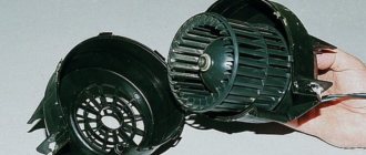
- The heater fan is removed.
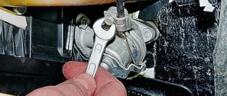
- The vacuum hose clamp is disconnected from the heater body.
- Remove the three spring clips that secure the front heater air intake housing.
Tip: to make it easier to unscrew and tighten the screws securing the air collector, you can remove the instrument panel, unscrew the screws securing the heater and lift it.
- Remove the screws securing the front housing.
- The front housing is removed.
- The radiator is freed from all hoses.
- The rear heater casing is removed.
- The radiator is removed from the heater.
- A new damper is installed so that the fork located on the damper axis is engaged with the lever.
- The damper must be in the raised position.
- The heater is reassembled in the reverse order of disassembly.
- Coolant is being added.
- The tightness of all connections and hoses, the operation of the dampers, and the entire heater are checked.
How the heater damper is replaced on a VAZ 2110 can be clearly seen in the video; the heater damper is replaced in a similar way on a VAZ 2112 model car.
Repair features
So, how should you repair your stove damper? First of all, you need to disassemble the damper and then replace it.
Disassembly stages
Knowing where the heater damper is located on a VAZ-2112, and having carefully read the vehicle’s instructions, you can understand what steps you should go through:
- The existing liquid, which is to be used for cooling, is first poured out completely.
- Disconnecting the car battery by disconnecting the minus terminal.
- Removing facing materials, windshield trim and soundproofing upholstery.
- Removing the fan that is installed inside the stove.
- Disconnecting the clamp that is part of the vacuum hose.
- Removing the heater air intake housing. These actions are sensitive and time consuming. If you first remove the dashboard, you can understand how to get to the VAZ-2112 heater damper in the shortest possible time.
- The next step is to remove all the parts used to attach the radiator.
- After this, the rear heater casing is disconnected.
- The radiator is pulled out of the heater.
- Now you can change the part itself. After a successful replacement, the problem associated with the fact that the heater damper on the VAZ-2112 does not work is successfully resolved.
Knowing how to remove the heater damper, you should ensure that reassembly is carried out correctly.
Assembly steps
The new part must be installed in a special way: the fork on its axis must be reliably engaged with the lever. This requires an open damper mechanism, so it is best to leave it raised. Otherwise, the element will not be able to open according to the optimal pattern and the stove will still not work. Only correct installation guarantees that the heater will function successfully.
If you are interested in how to change the VAZ-2112 heater damper, you should understand that everything will be done in the reverse order.
At the end of the procedure, it is mandatory to fill in the coolant and check the functionality of the part, the tightness of the hose structure and all connections. Then you need to turn on the heater and monitor it carefully.
Only if there is no such problem as the damper of the VAZ-2112 stove does not open, can you remain satisfied with the result of replacing the equipment.
Adjusting the heater dampers
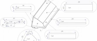
By adjusting the dampers with your own hands, you eliminate the supply of part of the air “to the glass” when the lever that controls the air flow is installed in the heater in the “chest” or “legs” position. The photo shows the damper adjustment control units.
Adjustment unit with control lever positioned vertically
2 – adjustable rod for installing the damper “in the chest” – “in the legs” 3 – fastening the rod “in the chest” – “on the glass”. To do this, you need to shorten the adjustable rod by three divisions, and use side cutters to bite off the protruding tip on it. After performing such operations, the heater damper will be in the desired position, and the heat from the stove will flow better in the given direction.