When you press the brake pedal, the cylinder is compressed by filling it with liquid. This, in turn, is supplied to the caliper under high pressure. As a result, the vehicle speed drops and movement slows down.
Often, during maintenance, car owners may be told that the clutch brake fluid needs to be replaced. You can do this yourself, which will allow you to save a lot on service station services. The brake system should be checked at least twice a year.
The service life of brake fluid is, for the most part, strictly limited and regulated by the manufacturer. It is advisable to change it twice a year in the spring. During replacement, it is advisable not to neglect banal safety rules.
2278-4-28-01
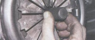
Remove the protective cap from the brake bleeder fitting.
Use a spanner wrench or an “8” socket to loosen the tightening of the bleeder fitting. We put a hose on the fitting, and immerse its free end in a container partially filled with working fluid.
An assistant should vigorously press the brake pedal all the way 4-5 times and keep it pressed.
Nuances of clutch operation
Often, drivers tend to associate unevenness and jerking when driving a car with clutch malfunctions. This logic is wrong in most cases.
For example, when a car shifts gears from first to second, the speed drops sharply. It is not the clutch itself that is at fault here, but the clutch pedal position sensor. It is located behind the clutch pedal itself. Sensor malfunctions can be eliminated through simple repairs, after which the clutch will again operate smoothly and without jerking.
Another situation: when changing gears, the car jerks a little, and when moving away it may stall. What could be the reason? Most often, the clutch delay valve is to blame. This valve provides a certain speed at which the flywheel can engage, regardless of how quickly the clutch pedal is "thrown" in. For novice drivers, this function is necessary, because... The clutch delay valve prevents excessive wear on the clutch disc surface.
Device characteristics
Using the clutch, it is possible to prevent sudden changes in load, which ensures a smooth start of the car from a standstill. The clutch also protects the entire gearbox from the loads of inertial moments that appear as a result of a sharp slowdown in the rotation of the crankshaft with the engine running at the moment when the driver changes gear. On Gazelle cars, a hydraulic clutch system is installed. It has gained wide popularity on many models of modern cars. The design of the hydraulic mechanism is based on the clutch master cylinder. Gazelle “Business” is also equipped with it. The main problem that the cylinder solves is the transmission of impulses from the pedal to the working element of the system. With the help of this unit, the machine starts. The mechanism also makes it possible to switch up and down gears.
Below we will look at the design of the clutch master cylinder. The Gazelle is a commercial vehicle, so at times it requires servicing. What problems happen with the clutch, how to repair, maintain and, if necessary, change this unit? Let's tell you about everything in order.
When is clutch bleeding required?
Bleeding the clutch hydraulic drive may be necessary in the following cases:
- Scheduled replacement of old fluid with new one.
Any liquid loses its properties over time and requires replacement. For brake fluid, which is also used in the clutch hydraulic system, the shelf life (from the date of manufacture), even when unopened, can be 1 year in plastic containers and 2 years in metal ones.
That is, the working fluid can still lose its properties regardless of whether it was used or not. The recommendations should be followed when it comes to replacing the working fluid in the clutch.
Clutch system repair.
Like any mechanism, the clutch is subject to breakdowns and wear during operation, as a result of which it may require repairs (replacement of cuffs, seals, repair or replacement of the cylinder, elimination of leaks in the line, etc.). And as a result of repairs, the hydraulic system depressurizes with the leakage of working fluid or the entry of air into it.
- Air entering the working fluid.
Air entering the line with the clutch fluid can occur both during clutch repair and fluid replacement, and due to air leaks through micro-holes in the hoses, through loose connections, worn rubber seals and cuffs in the master and working cylinders.
Point 3 deserves special attention: “Air getting into the working fluid.” This paragraph deals with malfunctions in which bleeding the clutch may not help, or may help, but only temporarily, since the malfunction will remain.
How quickly air gets back into the fluid will depend on the severity of the problem.
At the initial stage, while the microholes are very small, the penetration of air into the liquid occurs very slowly. But over time, wear increases, and along with it, the holes through which air penetrates increase. As a result, there comes a time when, after bleeding and removing air from the system, the clutch “disappears” again the next day or earlier.
How to modify the AMT clutch with a 1.8 engine on Lada Vesta and Lada XRAY
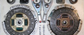
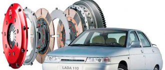
Jerking, jerking, shaking and vibrations when starting to move and when changing gears are one of the problems faced by owners of Lada Vesta and Lada XRAY with AMT and a 1.8-liter engine. If the LADA dealership recognizes such a case as covered by warranty, then the defective Valeo clutch disc is replaced with a new one of the same company (there is no alternative). According to reviews from owners, this solution is not durable. Soon they found a better replacement - a Sachs clutch disc.
Question to AvtoVAZ
via Za Rulem magazine:
You have to modify the design yourself.
Attention! The SACHS clutch disc is designed for installation on Chevrolet Niva cars. You install it on Lada Vesta and Lada XRAY (1.8L, AMT) cars at your own peril and risk
- Driven clutch disc Sachs (article 1878 002 205)
- Washers 8x14x1.5 (6 pcs.)
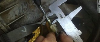
The Sachs clutch disc is approximately 1.5 mm thicker than the stock Valeo:
Therefore, 6 washers should be placed under the bolts that secure the basket to the flywheel. Otherwise, there may be problems with gear engagement.
On a Lada XRAY, you can replace the clutch disc without removing the gearbox and subframe, on the left side, by moving the box to the side:
After replacing the clutch disc, we adapt the clutch (some owners did without this, and there were no problems in the operation of the AMT after installing the Sachs clutch disc).
Installation on Lada Vesta (author):
Installation on Lada Vesta (author):
Installation on Lada XRAY (author)
Feedback from social networks:
Have you encountered similar problems? How did you solve vibrations at start-up on a 1.8-liter engine with AMT?
Let us remind you that on 1.6-liter LADA engines with AMT, in such a situation, the clutch kit is replaced under warranty. It uses new friction linings of the driven disk. They make switching and starting movement smoother. The risk of jerking and vibrations is reduced (see information letter No. 5-17 dated January 23, 2017).
Procedure for replacing the clutch Lada Vesta robot
- Open the hood.
- We remove the battery assembly.
- We dismantle the air filter, housing, air ducts.
- We snap off a number of sensor-controllers.
- In the car interior we remove the plastic inserts, gearbox selector, and electric drives.
- We hang the car using a hydraulic lifting mechanism.
- We dismantle the wheels.
- We drain the waste into an empty container.
- We dismantle the pallet protection.
- Remove the right drive shaft.
- We dismantle the starter and actuator.
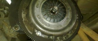
- We separate the flywheel and the body of the robotic box.
- We substitute the telescopic support.
- We remove the AMT from under the car.
- Remove the clutch module assembly.
- We carry out preventative maintenance and install new parts.
- We reassemble the structure.
How to replace clutch fluid on a VAZ 2101-VAZ 2107?
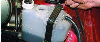
Draining: 1) First, before you start working, use a clean or slightly dirty rag to wipe the clutch reservoir, or just its cover, to make it more pleasant to work with.
2) Next, grab the tank cap with your hand, and thereby completely unscrew it and put it aside so as not to lose it.
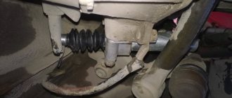
3) Next, if the crankcase protection installed on your car bothers you, let’s say it’s too big, then remove it to gain access to the clutch slave cylinder. (For information on how to remove the protection, see the article: “Replacing the crankcase protection”)
4) Now perform the following operation, to do this, again using a cloth, wipe the protective cap located on the fitting of the clutch slave cylinder and at the same time clean the cylinder fitting itself from dirt.
5) After the dirt has been removed, take a wrench and use it to unscrew the fitting itself by about 3 or 4 turns (At your discretion), and after unscrewing the fitting, at this time let your assistant help you, thereby pressing the pedal clutch several or even more times, generally until all the fluid flows into the container you prepared in advance.
Note! When pressing the pedal, be sure to warn the assistant that it may fail, that is, fall to the very bottom and not go back, then in this case, let him return the pedal to its place with his hand, bending it to do this and thereby lifting it!
Filling: 1) When all the liquid has been drained from the tank, then in this case tell the assistant that you don’t need to press the pedal anymore, and at this time you tighten the bleeder fitting that was unscrewed earlier so that the liquid no longer pours out of the working cylinder and always remained in it.
Note! At the very end of the operation, fill the clutch hydraulic reservoir with brake fluid to the required level!
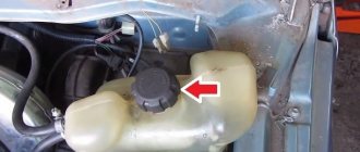
And after pouring the liquid before screwing the lid, visually inspect this lid for defects, and also check the compensation cavity, which is indicated by the arrow and which is also removed from the lid, so if after removal you see signs of rubber aging, signs of cracks and tears, then In this case, replace this cavity with a new one!
Advice! By the way! You can also replace the fluid in the clutch drive, displacing the old one, to do this you need to ask your assistant to add fluid to the reservoir as it is displaced, and do all this until normal, clean fluid begins to flow into the container you are holding!
Important! Be sure to bleed the car’s clutches when you finish replacing. (For information on how to bleed the drive, see the article: “Bleeding the clutch on a VAZ”)
A method for replacing fluid in brake circuits without bleeding.
This method is simpler than the first, pumping is not required, the liquid fills both circuits by gravity. The disadvantage of this method is the higher fluid consumption. And so, the tank is filled with fresh DOT-4 type fluid. The car is located on an overpass or inspection hole. The performer of the work must have time to monitor the increase in the levels of drained fluid in the containers simultaneously from all brake cylinders of four wheels, while replenishing the reservoir with fresh fluid; for this, unobstructed passage around the car will be required.
The hoses from all fittings of the brake mechanisms must be taken out into containers, the fittings must be turned out half a turn. The liquid will begin to decrease from the four-bottle tank. With 200 ml filling in the bottle, screw in the corresponding fitting. No pedal pressure required. After work, make sure there are no drops on the fittings (you may have to tighten them), wipe them dry, and put on the standard caps.
Clutch master cylinder operation
The clutch master cylinder works as follows. When you press pedal 21, pusher 14 moves piston 4, compressing spring 8.
As soon as the cuff 10 closes the bypass hole b, pressure is created inside the cylinder in cavity a, and the liquid passes through the hole in the fitting 7 and through the connecting tube 2 into the working cylinder 29, causing the movement of the piston 36, the pusher 27 and connected to it through the tip 24 and pin 23 forks 22 clutch release. The clutch disengages. At the same time, the tension spring 25 of the fork is stretched and the pressure springs 14 are compressed.
We recommend: Contact ignition system - what is it and what secrets does it keep?
When the clutch pedal is released, the latter returns to its original position by spring 75, and the piston 12 of the master cylinder, under the action of the return spring 8, moves after the pusher 17 until it stops against the washer 14. At the same time, the pressure in the system drops, and the clutch pressure plate changes under the action of the pressure springs , presses the driven disk against the flywheel again. The clutch engages. Moving the pressure plate until it stops against the driven disk causes the heel associated with it to move through the release levers and the thrust bearing resting against it.
Next, the thrust bearing and the associated clutch release fork move under the action of the tension spring 25, which constantly presses the pusher rod 27 against the piston 36 and moves the latter to its extreme forward position. In this case, the piston displaces liquid from the internal cavity of the working cylinder 29. The liquid through tube 2 returns to cavity a of the main cylinder.
When the clutch pedal is abruptly released, the fluid returning from the working cylinder to the main cylinder does not have time to fill the space vacated by piston 12, and a vacuum is created in cavity a.
Under the influence of this vacuum, liquid from cavity e (where it enters through hole c) flows into cavity a through holes d in the piston head, pushing back valve 11 and the edges of cuff 10. Grooves on the surface of cuff 10 facilitate the passage of liquid from cavity d to cavity a. Subsequently, excess fluid, as it enters from the pipeline, is forced out of cavity a through the compensation hole b into tank 3. The flow of fluid from the connecting tube into the clutch master cylinder stops as soon as the piston of the working cylinder, under the action of the pressure springs and the release spring of the clutch release fork, returns to extreme forward position.
Clutch release drive device
The stamped clutch pedal 21 is mounted on a welded bracket 12, fixed to the body with bolts 11 and studs 8 with nuts 7. The clutch pedal swings on an axis 16, which is fixedly fixed in the bracket 12. The pedal is secured against rotation by a flat that fits into a shaped hole in one of the cheeks pedal bracket.
The axial movement of the axis is limited by the cotter pin 13 and the shoulder of the flat. Two polyamide bushings 17 rotating on an axis, having collars at one of the ends, are inserted into the pedal hub.
The bushings have high wear resistance and do not require lubrication during operation. A rubber pad 31 is put on the pedal platform. The pedal is held in its original (rearmost) position by the force of the tension spring 15. In this case, the non-adjustable pusher 14, pivotally connected to the pedal with a pin 19, rests against the limiting washer 5, fixed in the axial direction with a locking ring.
In the initial position of the pedal, the piston 12 of the clutch master cylinder under the action of the spring 8 abuts its end against the washer 14. Between the pusher 14 and the piston 4 there is a constant gap of a = 0.2 - 1.0 mm, which is ensured within the specified limits by the selected dimensions of these parts and the limiting washers 5.
We recommend: Description and principle of operation of the ESC stability control system
The specified gap provides the piston of the master cylinder with the opportunity to take its original position (with the clutch engaged), guaranteeing communication between cavity a of the cylinder and the filling tank 3 through compensation hole b.
In clutch and foot brake control drives, pedal axles, polyamide bushings, pushers, pedal linings and fasteners are interchangeable. The clutch master cylinder is designed to create pressure in the hydraulic clutch drive system. The cylinder has a cast iron body 9 with an internal diameter of 22 mm with a figured flange; Two pins 18 are screwed into the flange, with the help of which the cylinder and pedal bracket 12 are attached to the front panel of the body. During assembly, up to four (as needed) adjusting shims 6, made of sheet steel 0.5 mm thick each, are installed between the cylinder body flange and the front body shield. These spacers help establish the initial position of the clutch pedal, which should ensure its full travel L until it touches the rubber floor mat, equal to 150-155 mm.
Rice. Clutch release drive: 1 — bracket for fastening the connecting tube; 2 — connecting tube; 3 — clutch master cylinder assembly; 4 — piston of the clutch master cylinder; 5 — limit washer; 6 — adjusting gasket; 7 and 28 - nuts; 8 — master cylinder mounting pin; 9 — supply tank for the clutch master cylinder; 10 — nut holder; 11 — bolt of fastening of the clutch pedal bracket; 12 — clutch pedal bracket: 13 — cotter pin for the clutch pedal axis; 14 — piston pusher of the clutch master cylinder; 15 — clutch pedal release spring; 16 — axis of the clutch and brake pedals; 17 — bushing for the clutch and brake pedal axle; 18 and 33 - washers; 19 and 23 - fingers; 20 and 32 — cotter pins; 21 — clutch pedal; 22 — clutch release fork; 24 — pusher tip; 26 — release spring for clutch release fork; 26 - lock nut; 27 — fork pusher; 29 — clutch operating cylinder; 30 — pin for fastening the working cylinder; 31 — pedal pad; 34 — protective cap; 35 — retaining ring; 36 — piston of the working cylinder; 37 — sealing collar; 38 — spacer mushroom; 39 — spring; 40 — air release valve; 41 — valve protective cap; 42 — tube fastening bracket; 43 — gasket
At the top of the master cylinder body there is a tank 3 made of translucent plastic. The reservoir contains a certain supply of brake fluid necessary for the normal operation of the hydraulic clutch drive. The tank is closed with a plastic threaded cap 1, in which there is a hole to communicate the internal cavity of the tank with the atmosphere, and a reflective plate is attached to prevent the brake fluid from splashing out through the specified hole. The flange of the strainer 2 rests on the end of the supply tank, which simultaneously functions as a damper for the brake fluid in the tank.
The nutrient tank 3 is attached to the main cylinder body 9 with a threaded fitting 4, which has a slot at the end for a screwdriver. The sealing gasket 5 after tightening the fitting guarantees the tightness of the connection between the tank and the cylinder body. Through the hole in fitting 4, brake fluid from reservoir 3 flows by gravity into housing 9 of the master cylinder.
A rubber sealing collar 13 is placed on the piston 12 located inside the cylinder, which prevents liquid from leaking out of the cylinder. The piston is cast from zinc alloy. There are six through holes in the piston head, covered with a thin steel ring-valve 11 and an internal working rubber cuff 10. On the outer surface of the cuff there is one annular and six longitudinal grooves. Spring 8 presses the cuff against piston 12, and the piston against thrust washer 14. The other end of the spring rests against threaded fitting 7, which closes the internal cavity of the cylinder body.
A rubber protective cap 16 protects the internal cavity of the cylinder from dust. The cap is tightly placed on the groove in the cylinder body and the pusher rod 17.
The clutch slave cylinder 29 is secured with two studs 30 and nuts 28 on the left side of the clutch housing. The internal diameter of the working cylinder is 22 mm.
The main and working cylinders are connected to each other by a bent copper (6×1 mm) or two-layer steel tube 2 with copper-plated inner and outer surfaces (6×0.7 mm). The spiral located in the middle part of the tube compensates for the change in the distance between the ends of the tube, which is inevitable when the position of the power unit, suspended on rubber cushions, changes relative to the body. In addition to being secured at the ends, the tube has two intermediate attachment points: on the left mudguard of the body using bracket 1 and on the engine crankcase using bracket 42. Rubber gaskets 43 are laid between the fastener and the tube. The ends of the tube have a double conical flaring, the shape and dimensions of which shown in the figure. Before flaring the ends, connecting nuts are put on the tube, with which it is then connected to the main and working cylinders.
Rice. Clutch master cylinder: 1 — reservoir cap; 2 - mesh filter; 3 - tank; 4 — tank fitting; 5 — tank fitting gasket; 6 — master cylinder fitting gasket; 7 — main cylinder fitting; 8 - spring; 9 — main cylinder body; 10 — sealing collar of the main cylinder; 11 — piston valve; 12 - piston; 13 - piston seal; 14 - thrust washer; 15 — retaining ring; 16 — protective cap; 17 — piston pusher; 18 — master cylinder mounting pin
The housing 3 of the working cylinder is a casting made of gray cast iron, having on one side an open cylindrical cavity into which a cast aluminum piston 7 with a rubber sealing collar b, a spacer fungus 5 and a spring 4 are inserted. The spring constantly presses the spherical surface of the fungus against the sealing edge of the cuff and through it the edge to the cylinder mirror, which significantly improves the seal of the working cylinder, especially when there is no pressure in the system (the clutch is engaged).
Rice. Flaring the ends of the connecting tube (tube cross-sectional dimensions: steel - 6 X 0.7; copper 6 X 1.0)
Rice. Clutch slave cylinder: 1 — valve protective cap; 2 — air release valve; 3 - cylinder body; 4 - spring; 5 — spacer fungus; 6 - sealing collar; 7 - piston; 6 — protective cover; 7 - retaining ring
The conical valve 2 screwed into the cylinder body 3 serves to remove air from the hydraulic drive system. Rubber cap 1 is placed on the valve head and protects the internal channel of the valve from clogging.
We recommend: Porsche Technical Center - the ideal service option
A pusher 27 is inserted into the spherical recess of the piston 36, which is adjustable in length. The pusher is adjusted by screwing it in or out of the fork tip 24. The position of the tip is fixed by the lock nut 26. The spring 25 of the clutch release fork 22 constantly presses the pusher to the spherical surface of the piston and, in the absence of pressure in the clutch hydraulic drive system, moves the piston to the extreme forward position. Since the piston 36 in the cylinder 29 can move in the direction corresponding to the clutch disengagement (to the right in the figure) only under the influence of the working fluid pressure, the formation of vacuum is eliminated, and therefore the penetration of air into the cylinder through leaks in the piston. Therefore, there is no need to maintain excess pressure in the connecting tube 2 and in front of the piston 36, which is usually provided by installing a double valve in the master cylinder, as is done in the hydraulic brake drive (see below). All parts of the clutch master cylinder, with the exception of housing 9 and fitting 7, are interchangeable with the corresponding parts of the brake master cylinder. Since the clutch master cylinder does not have a double valve, the body and fitting of this cylinder are different from the body and fitting of the brake master cylinder. To make it easier to distinguish between the clutch and brake master cylinders, their mounting flanges are rotated 60° relative to each other. A protective rubber cover 8 protects the internal cavity of the working cylinder from dirt.
Signs of a GCS malfunction
When problems begin with the master cylinder, it most often manifests itself as a hydraulic fluid leak. When the clutch pedal begins to work poorly, the first stage of diagnosis will be a visual inspection: any leaks on the cylinder and even just slightly moistened seals are a sign of a problem that needs to be solved.
Basically, when there are problems with the cylinder, the clutch pedal begins to sink or move slowly, and the pedal “sticks” in the lower position.
Another problem with the GCS is clogging of the holes in the tank lid. For normal operation, the level in the cylinder reservoir must rise and fall freely, and for this purpose, ventilation holes are provided in the cover. If they become clogged with dirt, the hydraulic drive begins to work with difficulty: the pedal becomes stiffer and does not return well to its original position.
How to bleed the clutch on a VAZ 2101-VAZ 2107?
Note! Always remember that you need to bleed the clutch together in a car, because it’s difficult to do this without the help of an outsider, but there is still a way out, so if you are going to bleed the clutch alone, then first read the entire article to at least visually understand how it’s done , and then run the video clip located at the very end of the article, and this video shows a visual process of bleeding the clutch, performed by just one person!
And it’s best to do all the work in a pit, because it’s much simpler and more convenient, but if it’s not there, then you can do the work without it, it’ll just be a little problematic!
1) At the very beginning of the operation, pour new brake fluid into the clutch reservoir, and then close the reservoir with a plug.
Note! The liquid must be filled strictly to the very top edge! (For more information on how to fill the brake fluid into the reservoir, and why you need to fill the brake fluid at all, see the article entitled: “Replacing clutch fluid on a VAZ”)
2) Next, take a small hose in your hands and put one end of it on the fitting of the working cylinder.
3) Then ask an assistant to sit in the car and press the clutch pedal about 5 times, for the last time let him leave the pedal fully depressed.
Note! Ask an assistant to press the clutch pedal sharply and at intervals of 3 seconds!
4) Meanwhile, while the assistant holds the pedal down, prepare an empty container into which you will drain the brake fluid with bubbles, and then lower the other end of the hose into this container.
5) Then loosen the fitting with a wrench and at this time brake fluid with bubbles will begin to drain into the container you are holding.
Note! As you already understood and this was already mentioned earlier, bubbles are air that should never be present in the brake fluid, otherwise the system will begin to malfunction, in general, we continue!
6) Now wait until the clutch reservoir containing the brake fluid is almost completely empty and then immediately tighten the bleeder fitting tightly, and let the assistant take his foot off the pedal.
Note! Be sure to pay attention to the words: “It will not empty almost completely,” so you don’t have to wait until all the fluid comes out of the reservoir; in no case should it fall less than 15 mm, otherwise you will be bleeding the clutch for a very long time and most likely the system it won’t even be pumped if you do this, because when the fluid is completely emptied from the tank, during this time air begins to enter the system, and therefore the clutch hydraulic drive will depressurize again, which will lead to constant pumping!
7) Now, as you already understand, when the level reaches almost to the very bottom, then stop the bleeding operation by screwing in the bleeder fitting and the assistant removing his foot from the pedal, and then again add liquid to the tank and repeat the entire bleeding operation again.
Note! Do this operation again and again until liquid begins to flow into the container without bubbles!
Additional video clip: More details about that? You can see how to bleed the hydraulic drive in the video below:
Clutch device for VAZ 2107, VAZ 2105, VAZ 2104, do-it-yourself repair
Clutch VAZ 2107, VAZ 2105, VAZ 2104
Bleeding the hydraulic clutch of VAZ 2107, VAZ 2105, VAZ 2104, Lada Zhiguli, Classic
Air in the hydraulic clutch of the Lada Classic is indicated by incomplete disengagement of the clutch, as well as “softness” and “sagging” of the VAZ 2105 clutch pedal.
To remove air from the hydraulic clutch of a VAZ 2107:
— clean the tank and bleeder fitting from dust and dirt; — check the fluid level in the hydraulic drive reservoir and add fluid if necessary;
Slave cylinder and clutch release fork VAZ 2104, VAZ 2105, VAZ 2107: 1 - clutch release bearing; 2 — ball joint; 3 — clutch release fork; 4 - pusher; 5 — adjusting nut; 6 - lock nut; 7 — tension spring; 8 — housing plug; 9 — fitting for bleeding; 10 — cylinder body; 11 - sealing ring; 12 — protective cap; 13 - piston; 14 - seal; 15 - plate; 16 - spring; 17 — support washer; 18 — retaining ring
— put a hose on the head of fitting 9 of the working cylinder and immerse its lower end in a vessel with hydraulic fluid (30–50 g); — unscrew fitting 9 1/2–3/4 turn, sharply press and smoothly release the pedal until the release of air bubbles from the hose stops; - Press the pedal and tighten the fitting as far as it will go. Remove the hose and put on the fitting cap.
If, despite prolonged pumping, air bubbles come out of the hose, check the reliability of the connections, find out if there are cracks in the tubes or leaks in the connections with the fittings. It is possible for air to penetrate through damaged sealing rings of the main or working cylinders of the VAZ 2104.
What to put in the clutch reservoir
download photo to your mobile phone Contents: - Operation, maintenance and repair manual for the VAZ 2106 car
Checking the level and adding fluid to the hydraulic clutch reservoir of a VAZ 2106 car
RECOMMENDATION Type of brake fluid: “Tom” or “Rosa” with a class of at least DOT-4.
WARNING Brake fluid is toxic. Observe safety precautions when working with brake fluid. Do not allow brake fluid to come into contact with wires, plastic or painted parts. If brake fluid gets on such parts, wipe them off immediately. Use only brake fluid recommended by the manufacturer of the VAZ 2106. Do not reuse fluid drained from the system - such brake fluid is contaminated, saturated with moisture and air. Fill the clutch reservoir with brake fluid of the brand already used in the system or one that is compatible with it.