I feel soon my blog will turn into a manual for repairing Lada electrical equipment... =/
In general the situation is like this:
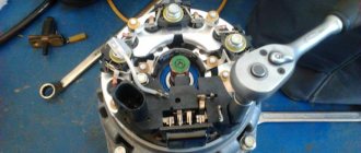
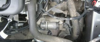
The turn signals on the car did not always work. Then they stopped altogether. When you turn on the turn signals, the light on the dash tries to blink, but nothing. The relay clicks.
So what if it clicks, I thought, and checked its functionality. I checked it by adding a new relay. And voila.
Only one thing confused me...
To the relay was insolent
Some kind of third-party wiring is attached. The owner was unable to find out its purpose.
For additional information to potassium growers:
I went to find out - it became interesting: 1) The principle of operation (yes - I didn’t know, I confess); 2) What could this wiring do there; 3) How can this relay be used in Solaris =)
1) Operating principle:
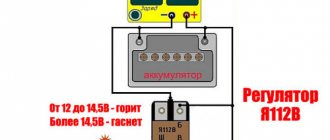
The turn relay has 3 contacts: 49, 49a and 31. 31 contacts - constant ground (-) 49 contacts - constant power (+) 49a contact - relay control.
When contact 49a was closed through the load (Light bulb/speaker/LED, etc.) to ground, the relay began to operate.
On Kalina, contact 49a goes to the emergency lights and turn signals. To the emergency lights, from this contact, the wiring goes without a break. Accordingly, the relay turns on without ignition.
Turn signals 49a receive contact only after the ignition is turned on.
This point was sorted out (personally, for myself, I understood everything I wanted). If you have any questions, I will be happy to answer them.
2) I still haven’t realized the meaning of this wiring. In fact, it was connected to the load. Accordingly, whatever was connected there, it made the relay work. Or vice versa. Perhaps they wanted a permanent plus. Perhaps they wanted a lot. But without thinking through his actions, the person spent extra money and time fixing the problem.
3) It was at this point that my imagination began to work, because for so long I had wanted to make myself a central brake light (additional, on the trunk lid), which would work in two modes) The circuit is insanely simple, reliable and interesting. So far I have not grown up to soldering microcircuits and programming them. That's why I invent what I have.
Current after the brake pedal, which goes to additional. stop, distributed with a relyushka. If no current is supplied to the relay, add. the signal works as standard.
If you apply current to a 5-pin relay (Relay (5)), which will be controlled by a button from the interior, then contacts 30 and 87 will close. The current (12V) will go to the turn signal relay (Relay (3)) and through it to the additional . light.
To prevent Relay (3) from being killed during normal operation, a diode is placed on leg 49a.
The advantage of this scheme is that in case of malfunction, the cause will only be in the relay. Replacing them is not a problem.
Soon I will try to create a prototype and subsequently install such a feature in my car.
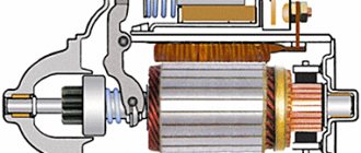
How does an electromagnetic-thermal relay work?
These devices are no longer used in modern cars. However, in older models they are still widely used.
The design of the electromagnetic-thermal relay is quite simple; it uses a circuit for connecting turn signals through an electromagnetic-type relay. It is made in the form of a cylindrical core, and a thin copper wire is used as its winding. At the top of the core there are two groups of contacts, and metal anchors are installed on each side. The first group of contacts closes the circuit where there is a control light located on the instrument panel. With the help of other contacts, the circuit with the lamps in the direction indicators is closed. They are the ones who provide the flashing mode.
Electronic relay: circuit and principle of operation
The design of the electronic turn signal relay consists of two main parts. From a standard electromagnetic relay that performs switching and an electronic key that provides a certain frequency of operation of this device.
The nichrome string has been replaced with an electronic key. With its help, voltage is supplied and removed from the winding of the electromagnetic relay at certain intervals. The key is based on microcircuits or discrete elements. They are components of the master oscillator and control circuits.
The operating principle of an electronic relay is very simple. When voltage is applied to the relay, the master generator is switched on. With its help, control pulses with different frequencies are generated, which are supplied to the control circuits. By means of pulses, the current passing through the winding of the electromagnetic relay is supplied or interrupted. Such actions cause the anchor to alternately attract or lower. As a result, the contact groups close or open at a certain frequency, ensuring the same flashing of the signal lamps.
All electronic elements of the relay are mounted on a separate board. The electromagnetic relay is located above the board. Both of them are housed in a plastic case. The contacts are brought out from below or from the side. For fastening the housing there are holes and eyes for bolted connections.
Each electronic turn relay has undoubted advantages over other designs. They have proven themselves to be high-quality and technologically advanced devices, manufactured on the basis of modern circuits that are characterized by increased reliability. The technical characteristics of these devices remain unchanged, regardless of the service life.
Turn signal diagram
Turn signals are very important in busy modern traffic, and malfunctions cause great inconvenience. The turn signal design on domestic and imported cars is almost the same. Depending on the year of manufacture of the car, electromagnetic-thermal or electronic relays are used as a breaker. The principle of connecting all relays is almost identical. Currently, some imported cars and VAZ 2170 Priora do not have a turn signal relay; its function is performed by an electronic control unit for power accessories. This article only discusses the classic turn signal design.
Consider a turn signal circuit using a relay. In these circuits, the relay is connected in series with the signal lamps through the turn switch. An exception is the connection diagram of the turn relay type RS 950 and its analogues used on trucks. We will return to the connection diagram for this relay a little later. First, let's look at the connection diagram for direction indicators with an electromagnetic-thermal relay of type RS 59. As can be seen from the figure, the diagram is very simple.
When the ignition is turned on, power is supplied to the turn relay, and when the turn switch is moved in one direction or another, the relay is connected through the signal lamps to the minus. In this case, when the relay contacts close, the lamps light up, and when they open, they go out. The use of an alarm system with this relay is not possible due to its heating during operation and rapid failure due to the high power consumed by the lamps. In addition, this relay will not work with diode lamps, since the current consumption of these lamps is not sufficient to close the contacts. The operation of such a relay is described in detail in the article “VAZ-2101 Turning Relay.” The following connection diagram with an electronic relay, except for the RS 950 type relay and its analogues. Electronic relays, as a rule, have from 3 to 5 pins, and their connection diagram is fundamentally identical to that described above. Since electronic relays allow switching large currents, unlike electromagnetic-thermal relays, it becomes possible to activate an alarm through them. To implement this, the circuit additionally includes an alarm button. The methods for enabling it on different cars may differ, but not significantly. In turn signal mode, power to the relay is supplied through the hazard warning button contacts from the ignition switch, and in hazard warning mode directly from the battery. Also, in the emergency mode, the button connects the output of the relay signal lamps with its contacts to the signal lamps, bypassing the turn switch. Connecting an electronic relay from an electromagnetic-thermal one differs only in the presence of a terminal connected to the vehicle ground.
The RS 950 type turn relay is included in the turn signal circuit before the turn switch, in contrast to a simple electronic relay. This is due to the way the control lamps are connected. A relay consists of an electronic part that controls an electromagnetic relay. When turning on one of the sides of the car, current pulses from the electromagnetic relay are supplied to the turn switch, then through the turns relay terminals, electromagnetic relay coils or warning lamp reed switches, they are supplied to the warning lamps. Below is a schematic diagram of connecting the relay.
admin 03/12/2013
“If you notice an error in the text, please highlight this place with the mouse and press CTRL+ENTER” “If the article was useful to you, share the link to it on social networks”
Turn signal relay pinout
During operation, the standard turn relay may fail and in this case it needs to be replaced. Incorrect operation of the device becomes noticeable, especially when the control light stops lighting up. The main cause of the malfunction is incomplete closure of the device.
In other cases, the relay begins to function unstably, and the relay contacts close at different time intervals. In some cases, the volume level of the sound accompanying the operation of the device is significantly reduced. This can create a serious problem on the road when the device is activated without the driver noticing due to accidental contact while driving the vehicle.
These shortcomings are eliminated by replacing the standard device with an electronic design. In this case, the turn signal relay is connected according to the standard diagram shown in the figure. Pin No. 1 is positive, the second pin connects to the turn switch, the third connects to the warning light, and the fourth connects to ground.
All connections and contacts must be reliably insulated using electrical tape and cambric, which is a hollow plastic braid. This eliminates possible short circuits with other conductors. Certain inconveniences are created by the plastic housing of the electronic relay, which does not always fit in its standard location. However, home craftsmen quite easily overcome this difficulty and find the most optimal technical solution.
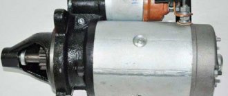
Replacing the turn signal relay for a VAZ 2107
The design of the relay does not provide for the possibility of its repair. If a malfunction is detected, the part must be replaced.
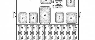
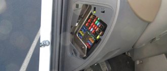
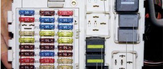
If the relay is located in the mounting block, to replace it, simply follow these simple steps:
- open the cover of the mounting block;
- pry with a screwdriver and remove the old relay;
- install a new relay;
- close the cover of the mounting block.
- Unscrew and remove the button (handle) of the daily mileage counter.
- Remove the decorative handles from the interior heater control levers.
- Remove the decorative plug from the dashboard mounting screw.
- Unscrew the screw.
- Unclip the dashboard fasteners by prying it up with a screwdriver.
- Unclip the wire connectors from the instrument panel.
- Unscrew the speedometer cable by hand.
- Remove the dashboard.
- Unplug the wire terminals from the relay by turning.
- Unscrew the relay mounting nut.
- Connect wire terminals
- Reinstall the relay and tighten the mounting nut.
- Connect the wire terminals to the dashboard.
- Screw the speedometer cable to the dashboard.
- Place the panel in place by snapping the fasteners into place.
- Tighten the screw that secures the dashboard.
- Install decorative handles on the heater control levers.
- Screw on the trip odometer handle.
- Install the decorative plug onto the self-tapping screw.
After this, you need to connect the ground wire to the battery. Replacing the turn signal relay is now complete.
DIY turn relay
Sometimes situations arise when the standard turn signal relay fails and it is not possible to purchase a new device. In such a situation, you can try to make a turn signal relay with your own hands to provide the car with the necessary signals. The simplest electronic devices that you can create yourself are simple and easy to use, operate smoothly and reliably. High accuracy is achieved through the use of PWM controllers used in all circuits.
The simplest replacement for an electromagnetic relay is designed for a maximum load power of 150 W. It is connected to the positive terminal. If the IRFZ44 field switch is replaced with the IRF3205 model, then 200 W can be connected. This simple circuit ensures high accuracy of operation. The blinking frequency does not depend on the power of the light bulbs, so LED, halogen and other lamps can be included in the circuit.
The frequency of flashing is directly related to the capacitance of the capacitor. As the capacity increases, the light bulb will blink more rarely, and, conversely, decreasing the capacity will lead to faster blinking. The low-power 1n4148 diode can be replaced by any similar element. When the circuit reaches a power of 80 W, a slight generation of heat is observed in the field-effect transistor area. This means it is ready to use.
There is another simple circuit of a turn relay with a coil - simple, reliable and inexpensive. It is capable of lighting both regular light bulbs and LED ones and is designed for 12 V. The contacts are connected according to the principle of a regular switch, that is, in series with the light bulb. The LED is installed in the circuit as an indicator during commissioning work. The device parameters are adjusted by changing the resistance of the resistor.
Conclusion
The turn relay is a small but extremely important component of a car's warning light system. It allows the driver to be more predictable for other road users, which, of course, has the best effect on traffic safety and, to some extent, comfort. If the relay fails, the problem cannot be ignored under any circumstances. Fortunately, the relay is not an expensive component of lighting systems, so a car enthusiast can take two devices at once with almost no loss of budget - the second one will be in the trunk, garage or at home in reserve. This is exactly what we advise you to do.