Connecting the central lock
First you need to study in detail the connection diagram for the central locking on a VAZ car - 2115,2114. Finding it is not a problem by searching on the Internet.
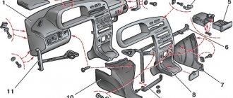
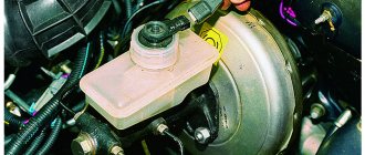
The central locking control module is located on the left under the dashboard. Looking there, you will find six wires coming out of the module housing. To install the alarm, you must disconnect the blue and brown cords. As a result, we get a connection corresponding to the following diagram:
Before connecting the alarm, you should make sure that it is not a toggle switch installed on the driver's door, but a standard actuator with five outputs. Otherwise, you will need to install an actuator, which is quite problematic.
On VAZ -2115,2114 cars, the white wire, which is connected to the seventh terminal, is usually responsible for unlocking. If there are no connections at terminals 7 and 5, then the eighth terminal is connected to the brown cord. It is this cord that is responsible for unlocking in this case.
Terminals number five and six are responsible for locking the lock. This arrangement of contacts is typical for almost all blocks of the “ninth” series.
For some reason, none of the instructions for alarms ever indicate that installation requires the purchase of additional elements.
We will definitely need:
- Two to three 1N4001 diodes per Ampere
- One 1N5401 3 Ampere diode
- Two 4 or 5 Ampere diodes if there are no separate outputs for turn signals.
When installing a Starline alarm system, the task is greatly simplified, since significantly fewer additional parts are needed.
The central locking in the car does not work
Central locking (CL) is a very convenient thing that allows you to lock or unlock all the car doors at once with a slight movement of your hand. However, sometimes this system does not work correctly or does not respond at all to turning a key or pressing a button. What could be the reasons for a central locking malfunction?
Often the central locking, especially on domestic cars VAZ-2110, VAZ-2114, VAZ-2115 and their derivatives, begins to act up. It manifests itself like this: when you close the driver's door with the key, the other doors do not respond. If you move the key a little, the central locking works. Why is this happening?
Contacts in the main drive do not close
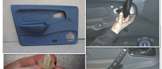
The central locking, powered by the driver's door lock, functions as follows: an electric drive is installed in the specified door, which not only controls its lock, but also sends signals to the central locking unit. The block distributes corresponding signals to drives installed in other doors.
The control actuator in the driver's door has five wires
For these purposes, an actuator is installed in the driver's door not with two, as usual, wires, but with five. Via additional wires, the drive “communicates” with the central locking unit. When the lock is locked, the driver's door control rod lowers and closes certain contacts inside its housing. The central locking unit receives voltage and gives a command to the lock drives of other doors to close. The same thing happens when opening, only the voltage flows through other wires and through other contacts, making it clear to the central locking unit that it needs to send a command to unlock the door locks.
In this case, the contacts inside the control drive may not always close at the right time. For example, this may occur due to improper adjustment of the linkage that connects the lock button on the door and the electric drive itself. That is, the button may already rest against the casing, preventing the rod from lowering further, but the contacts in the drive have not yet closed. Accordingly, it seems that the lock is locked (it may actually be locked on the driver’s door), but the other doors will not lock, since the rod needs to be lowered another couple of millimeters.
The same phenomenon occasionally occurs on the VAZ-2110, when the button gets pinched against the door trim and also prevents the rod from descending to the required depth. The most important “trick” is that this lowering may be enough for the mechanical lock to lock and it seems that the door is locked, and accordingly thoughts come about a malfunction of the entire central locking system. This is wrong.
When the central locking behaves this way, first of all you should make sure that the button is lowered all the way. To do this, with the door open, click the lock latch two clicks, simulating a closed door, turn the key and try to lower the button with your hand. If the central locking works, then you need to release the lock button from its tight contact with the door trim or adjust the linkage from it to the control drive.
Central locking fuse blown
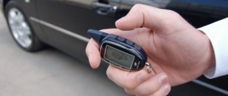
If the central locking still does not respond to locking and unlocking the driver's door, then the problem is most likely electrical. The simplest reason is a blown fuse. Moreover, in the case of a central lock, it can burn out not only from a short circuit, but also from a normal overload. This happens when it is too difficult for the drives to move the lock rods, for example, due to improper adjustment of the rods or congealed lubricant in the lock. frozen locks using the key fob .
Broken central locking wires
Another reason why the central lock may not work completely or partially is a broken wire. Moreover, the wires break, as a rule, in those places where they are subject to bending loads - the entrance from the body pillar to the door. The driver's door is the most frequently opened door in any car, and the control drive is located there. This means that it is enough to break at least one wire that enters it from the rack and relates to the central lock, and the entire locking system may begin to work incorrectly.
Schematic diagram of the electrical system of the central locking system
It is quite easy to determine this malfunction. You need to carefully remove one of the ends of the rubber corrugation along which the wires enter the door, and pull the necessary wires towards you. Which wires are responsible for the central locking can be found out from the car's electrical diagram. If this information is not available, you can pull all the wires separately.
The point of such a check is that the broken wire will be pulled out of the common harness. Here you can also pull out the other end to connect them and thus repair the central lock. You can connect the wires by twisting them, or you can use male-female terminals
.
Naturally, any such connection will need to be wrapped with electrical tape
.
Wires can be broken in other places, but this is rare. If this does happen, you need to use a multimeter to call the entire electrical network of the central locking system and find a break. This requires some knowledge of automotive electrical engineering and the ability to use a multimeter.
Central locking unit burned out
Another reason why the central locking may not work is the combustion of the central locking unit. To diagnose it, you also need to use a multimeter and determine the presence of voltage on the contacts to which the drives of other doors are connected. The control drive in the driver's door must at this time supply current to the corresponding contacts of the unit (the lock must be unlocked or locked with a key).
The central locking activator is faulty
And finally, the reason for the central locking failure may be in the control drive itself (they are also called activators), or more precisely, in its contact group. The contacts may oxidize or break off, and then the drive will not be able to send the appropriate signal to the unit - the other doors will not respond to turning the key in the driver's door lock.
In this case, you will need to replace the electric drive with a working one. Find out what drive is in your car and buy a similar one. If the drive is a regular common activator, then buy the same one. The most important thing is that it has five wires, because activators with two wires are responsible only for locking and unlocking the lock and do not send signals to the central locking unit.
Connection diagram
After carefully studying the alarm installation instructions, you can find the following connection diagram:
In this diagram, the designation X2 indicates a six-pin connector. It must be connected according to the diagram above. If you need to install an additional actuator, then it is better to use the diagram given in the instructions.
Now let's figure out how to connect the door sensors. For this purpose, there is a special wire in the connector marked X3.
Tapping into wires
Next to the driver's door, there are two wire harnesses running right along the floor. One of them has a cable coming from the parking brake and two wires to the turn signals. The second harness contains the door switch cable. This is where you need to start connecting. To do this, remove the sill trim along with the side panel. They are attached using self-tapping screws that must be unscrewed. Having done this, you can see the wiring harness shown in the photo:
This harness goes to the dashboard. We are interested in the door switch cable. If a 1N5401 diode is inserted into the wire break, the current should flow towards the limit switches. And the second diode 1N4001 is connected as shown in the figure.
The following figure shows the second harness:
At the same time, taps are made from the blue cables and the cords are pulled to the place where the alarm will be installed. And the handbrake wire is cut, and a 1N4001 diode is soldered into the cut with the cathode towards the switch.
Connecting autorun
The VAZ-2114 models use an ignition switch with three terminals - 15 (blue wire), 30 (lilac) and 50 (red). Terminal 30 is connected to the battery. When you turn the key, blue wire 15 is connected to this terminal. The third terminal is responsible for the starter.
As it is written in the instructions, it is quite possible to power the alarm from contact 30, from which the lead is made. And the cable from connector X1, yellow, is connected to connector 15.
After all the actions taken, the connection of the tachometer remains. In this case, a loop antenna and a reading device are combined. Connector X3 has a gray-black outgoing wire. It is connected to the tachometer as shown in the VAZ dashboard diagram:
This will allow the alarm to control the speed. And at the very end we connect the ground from the main unit. This is a black cord from connector X3.
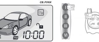
Settings
Only autorun functions can be configured. To activate programming mode:
- Disable security
- The ignition key is set to position 0.
- Then press the Valet key six times in the main block.
- Turn on the ignition
- After six beeps, use the same key to select the desired function, and use the key on the key fob to select the desired value.
The optimal settings for VAZ - 2115.2114 will be the following: function 12 - set to value 3, function 11 - value 4, function 9 - value 3. To select value 4, press and hold the third button until the melody is played.
After playing, press it again. To check the correct connections, perform the following steps:
- Disconnect the yellow cord from block A91 to terminal 15 for a while.
- The engine is started using the ignition key
At the same time, the alarm indicator should blink.
Subscribe so you don't miss anything important
The central locking VAZ 2114 (hereinafter referred to as CZ) is a mechanism that ensures the simultaneous closing or opening of all four doors in the car. This option is very convenient; it eliminates the need to reach out and lock the doors manually every time. Such centralized control comes in handy when installing car alarm systems, which significantly expands the possibilities and variations of the use of the locking mechanism.
Content
Other system failure options
The central lock itself (abbreviated as CZ) is a special locking mechanism that ensures all doors close at once. This device significantly increases the operating comfort of the car, as it eliminates the need to lock it manually. When installing an anti-theft alarm system, the functionality of the central locking system increases significantly.
The lock functions regardless of whether the power plant is turned on or not - it receives power directly from the battery.
As a rule, breakdowns of the locking device lead to certain difficulties with:
- closing individual doors;
- seizures;
- repeated slipping of the mechanism, etc.
There are several most common reasons that cause this kind of trouble, and we will talk about all of them below.
By the way, not all car owners know where exactly the central locking is located in their VAZ-2114. You need to look for it directly in the driver's door. An electric drive is also installed here. Other elements are distributed between other doors. The control unit (the brain of the central locking system) is located behind the dashboard.
To begin with, it will be useful to find out where the immo is located, because if this device does not work, to disable it you need to gain physical access to the device. In VAZ 2115 cars, the immo is located behind the center console, to the right of the steering wheel.
Today there are two types of devices: contact and non-contact. Contact systems are controlled using keys, while contactless systems are controlled using special chips built into a key fob or card. In the case of VAZ cars, immos are installed only on injection versions of cars.
Principle of operation
In what cases do you have to disable the anti-theft installation:
- If you are dealing with a manufacturing defect, that is, a defect. In particular, we are talking about the first versions of cars on which such devices were installed. In later variations, VAZ engineers added the function of alternative engine start, bypassing the protection. But you need to take into account that in this case the option will work only once; if a failure occurs, you must enter the access code, then activate the function and press the gas pedal a certain number of times.
Moreover, this operation will need to be repeated 6 times. For example, if your password is 123897, then first you press the pedal once, then twice (after a short period of time), then three more times, then eight times, etc. This function is described in more detail in the service manual.
- If the battery is completely discharged, the control unit may record this as an error, which will not allow the engine to start in the future. As mentioned above, the control module and the immobilizer interact with each other through a diagnostic line. So if the circuit loses power, it is perceived as an error.
- Also, blocking can be carried out due to the control unit. For example, if a driver uses diagnostic equipment to test vehicle systems, a code failure may occur. The ignition must be turned on. Moreover, the cause of the failure may also be due to interference emitted by the smartphone.
- Also, the need to bypass immo may arise as a result of banal failures in its operation (author of the video channel IZO)))LENTA).
VAZ 2109 Central locking does not work. Wiring repair.
VAZ
2109 2005 injector. Problems with the alarm. The central locking does not work. Definition of signaling.
In this case, there is no need to install an alarm, and the process of installing and connecting the actuators is similar to the example above. The only differences are that you will have to lay additional wires for the driver’s door electric lock, and also “figure out” the connection diagram for the central locking control unit.
Central locking diagram for VAZ 2114
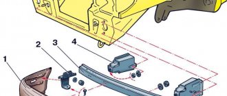
The system consists of the following components:
- mounting block;
- 8 amp fuse;
- 4 gearmotors (one in each door, and the one in the driver's door has a contact group);
- central locking control unit;
- wires (red, black, blue, yellow) and plugs;
- rods that are located in each door;
- limit switches that signal the current state of the door (open or closed).
Let's make the alarm system and central locking together
Any modern alarm unit is equipped with two relays connected to the central locking control unit. One relay is opening, the second is locking, and the circuit in the general case looks like this:
Control of central locking by supply of “mass”
In our case, the green and white cords coming from the signaling unit will be required, as indicated in the diagram. However, they will not be the only ones needed. We will connect the relay contacts to breaks in the standard wiring. This means there will be not 2, but 4 cords.
Connection diagram for VAZ central locker
Take another look at the diagram published in the first chapter. We will connect the relay to the gap in the white and brown wires going from the microswitch to the central lock control unit. And it is obvious that it is easier to break these wires near the 8-pin connector. The same one shown at the beginning.
To avoid any questions, we will show you what should happen as a result:
Connection diagram, central lock VAZ
The common contacts are connected to the wires coming out of the microphone. The white cord continues with the brown wire coming from the door, and so on. Normally closed contacts are also used, along with normally open ones. These are the features of connecting to the VAZ central locking system.
An approximate sequence of actions performed by the installer:
- Make and lay a 4-core cable running from the signaling unit to the 8-pin connector;
- Connect the cable on the side of the alarm unit (see the last diagram);
- Near the 8-pin connector, disconnect the white and brown wires coming from the microswitch (pins 5 and 7). The main thing is not to confuse them with the wires going to the triangular connector “C”;
- Make connections to the broken wires, white and brown. That's all.
We have given this sequence to emphasize once again that the relays are switched on between the microphone and the central lock control unit. There is no need to connect any additional devices. As a result, the alarm system will be able to control the state of the locks.
Remember that installation is performed by removing the negative terminal from the battery.
All wires added to the car structure must be protected (use heat-resistant tubes or electrical tape). Twisting is not the worst method to connect two wires. But it's even better to use soldering.
An interesting nuance from practice
It would seem that if a person has experience working with electrical equipment, he can do everything according to the instructions given. As a result, if no mistakes are made, you may encounter an interesting phenomenon. Instead of closing, there will be a short-term locking followed by opening. And vice versa. What to do in this case?
Take a look at what exactly may be present in some of the configurations:
Cheaper - no driver actuator
The driver's door may not have an actuator. And then, it is useless to connect the signaling system to the control unit. There is no actuator, which means there is no one to close or open the door and move the microphone lever. Let's say the locks are closed, and then we remove ground from the brown wire and we get the following: the white wire is on ground, unlocking occurs.
We note the following: installation can only be carried out when you are sure that there is an actuator in the driver's door.
There were configurations where only a microswitch was installed. There is no need for arrogance here - adding an actuator will be difficult, since standard wiring must go to it. As you understand, it may not be available from the factory. And it’s unclear what to do then.
There remains one unanswered question - where exactly the central locking control unit is located. In these VAZ models, if there is a central locking system, then there is also a control unit. And it is located under the torpedo cover, next to the driver, on the right:
VAZ-2110, BU TsZ
We remove the “beard” of the torpedo and look at what is on the upper right. On the same plane with the radio connector there are two boxes attached - the one we need, as well as the immobilizer (if there is one).
We would be lying if we did not say that in reality there is another option for installing the alarm. Standardly, only two power cables go to the actuators. Having a power outlet equipped with a fuse, these cables are connected directly to the alarm relay. This option, as you might guess, is not recommended. Imagine what would happen if the alarm system broke. The central lock must remain, but in this case this will not be done. Happy connection!
Where is the central locking of the VAZ 2114
The central locking system is located in the driver's door, just like the electric drive. If we talk about the system as a whole, it is distributed over 4 doors (in some cases it also extends to the trunk), and the central panel (control unit).
Testing and diagnostics
conclusions
In this article, we touched upon only some of the most common problems associated with the operation, repair and maintenance of a centralized lock. Despite the fact that the node has plenty of problems, restoring its functionality is not a difficult, much less an impossible task. Usually, to achieve smooth, efficient operation of the system, only practical skills are missing. After receiving them, you will be able to repair any complexity! If you want to install the central locking on a VAZ 2114 yourself, then here is a video instruction:
Content
In order to protect your car from theft, you can equip it with a device such as a central electronic lock. To do this, it is not at all necessary to contact a service or specialized workshop, because in fact, its installation is much simpler than it seems at first glance. In today's article we will talk about how to install central locking on a VAZ 2114 and how to avoid possible mistakes.
Alarm system with central locking VAZ 2114
What does the relay kit with fuse box do?
VAZ 2114, 2115, 2113 technical characteristics. trunk volume of Lada 2114
Why the VAZ-2110 central locking does not work and its repair
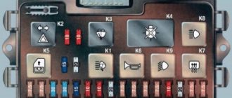
Layout of fuses and relays in the main mounting block of the VAZ-2110
The above diagram describes the location of the main relay kit and fuse box. The following elements are located here:
- K1 is a type of relay responsible for monitoring the health of a set of light bulbs;
- K2 – this component is associated with the operation of the front pair of wipers;
- K3 – behind this designation lies a breaker relay that regulates the operation of the repeater and the vehicle’s alarm sign;
- K4 and K5 – a pair of relays for the injector, which is responsible for turning on the low/high beam headlights of the VAZ-2110;
- K6 - an additional type of relay required to replace one of the burned out ones from the main unit;
- K7 - this element is responsible for turning on the heating function on the rear window;
- K8 - like K6, is a backup relay.
Tip: If you notice the main signs of a faulty oxygen sensor. You should look at the fuses first. If everything is in order in the mounting block, then you should seek help from a car service for diagnostics.
Lock connection diagram
In order to be able to install central locking on VAZ cars, the manufacturer equipped them with a special BUBD control module. You can find it directly under the torpedo, on its left side. If this module is missing, it will simply not be possible to install the device, so before you buy an electronic lock, you should first find out whether the module is installed on the car.
Control module
The connectors of this module are equipped with 6 wires of different colors as standard. If you are installing an alarm system on a VAZ 2114, you will need to turn off brown and blue in order to get the following connection diagram:
Before you begin installing the lock, you should make sure that five-wire actuators are installed in the car doors. If it turns out that ordinary switches are installed instead of them, then it will not be possible to connect the alarm.
Another important point to remember is the need to purchase additional electronic components that are not included in the alarm kit.
These include:
- diodes 1N4001 for 1 Ampere - 3 pieces;
- three-amp diode 1N5401;
- any diode rated for a current of up to 5 Amps (only if there are no separate outputs for turn signals).
Diode wiring
Once these components have been purchased, you can begin connecting the alarm. To do this, you should carefully study the drawing with the connection plan included in the instructions (this diagram of the VAZ 2114 central lock is duplicated below) and carry out the entire installation procedure in accordance with it. So, in the diagram, the index X2 indicates the six-pin control connector (BUBD), which was mentioned at the beginning. This is where you should start connecting, guided by the same “native” circuit.
After the lock is connected, all that remains is to insert into the wires in order to connect the alarm to the door sensors.
Connecting door limit switches VAZ 2114
It is done in the following order:
- Remove the sill trim along with the side panel by unscrewing their fastening screws.
- In the exposed wiring harness, find the cable going to the door limit switches (it has a white and black color) and solder a 1N5401 diode into its gap so that the direction of possible current flow is only towards the limit switches.
- In the second wiring harness, find two blue cables, from which you should make taps (using a wire of the same cross-section) and stretch them to the location where the alarm is attached.
- Cut the handbrake wire and solder a 1N4001 diode into its gap with the cathode towards the limit switch.
Tapping into wires
If necessary, you can make an insertion into the wires even before connecting the alarm to the connectors - this will not affect the functionality of the electronic equipment in any way.
The next step is to connect autorun. To do this, you will need to power the alarm to terminal 30 of the ignition switch, and connect the yellow cable coming from connector X1 to its 15th connector (according to the connection diagram).
After the alarm is connected to the on-board power supply, you will need to connect it to the speed sensor by connecting the gray-black wire coming from connector X3 to the tachometer. After this, all that remains is to connect the black wire X3 to the ground connector in the main unit.
At this point, the installation of the central lock can be considered complete.
Experts' opinions
Many experts who have encountered the problem that the central locking on a VAZ-2114 does not work argue that all problems with the device should be divided into certain categories. Below we will look at each of them.
- Complete device failure.
- Partial lock failure.
- Operation malfunctions due to mechanical, electrical or other defects.
If a problem occurs with the central locking, the car owner must independently determine which of the above categories the breakdown falls into. Therefore, repairing a fault should not begin with disassembling a particular unit - it is enough to conduct a thorough diagnosis of the equipment. Thanks to the diagnostics carried out, the car owner will not only reduce the time spent searching and solving the problem, but will also reduce the monetary costs of repairs.
Settings
After the alarm system on the VAZ 2114 is fully connected, its final configuration should be performed.
It is carried out as follows:
- Disable security.
- Set the ignition key in the lock to o.
- Press the button labeled Valet 6 times in a row.
- After the step marked “3”, immediately turn on the ignition (6 beeps should sound).
- Using the Valet button, select the required function (their list is given in the table below). To set it to the required value, press the corresponding key on the alarm key fob.
In this case, the most optimal (recommended) settings will be the following:
- for function 12 - value 3;
- for function 11 - value 4;
- for function 9 - value 3.
You can check whether the alarm is connected and configured correctly as follows:
- Disconnect the yellow cord coming out of block A91 from terminal 15 of the ignition switch.
- Turn the ignition key and start the engine.
- Pay attention to the alarm LED - if connected correctly, it should blink continuously.
The last thing I would like to talk about today is the importance of correctly connecting the tachometer, which directly affects the operation of the autostart.
To avoid errors, it is recommended to make this connection strictly in the following order:
- connect the red wire from the BUBD connector to the positive 12 volt terminal;
- connect the black wire of the 18-pin connector to the vehicle ground;
- Connect the gray-black wire of the same connector to the wire coming from the tachometer.
If you then turn on the ignition, then if the tachometer is connected correctly, the alarm indicator will begin to blink evenly.
Useful video
You can glean additional useful information from the video below:
Published July 05, 2019
How to quickly, easily and most importantly correctly disable the immobilizer on a VAZ 2115?
All modern cars, including cars from the domestic automobile industry, are equipped with immobilizers. Immo. This is an anti-theft device that allows you to block the engine in the event of a car breakdown. But like any other electronic device, over time this device may malfunction or cause problems, in which case car owners will have to turn it off. How to disable the immobilizer on a VAZ 2115 with your own hands, we will talk about this below.
general information
Firstly, it will be useful to know where immo is located, because if this device is not working, you need to get physical access to the device to disable it. In VAZ 2115 cars, immo is located behind the center console to the right of the steering wheel.
Today there are two types of contact and non-contact devices. Contact systems are operated by keys, and special circuits built into the key chain or card are used to operate contactless ones. As for VAZ cars, immo is installed only on injection versions of the car.
How does it work
The operating principle of this device is based on communication between the control unit and immo. The anti-theft device transmits data to enable or disable the starting power supply. If disabled, the system automatically blocks the ignition circuit via the fuel pump and therefore the engine will not be able to start. That is, without initializing the power supply it does not work
READ Vw Passat B6 Which Engine to Choose
When should I disconnect?
In what cases do you need to disable the installation of the anti-theft system:
- If you are dealing with manufacturing defects, this is a disadvantage. Especially, this applies to the earliest versions of vehicles on which such devices were installed. In later versions, VAZ engineers added an alternative engine starting function, bypassing the protection. But you must keep in mind that in this case the parameter will only work once, if a failure occurs, you need to enter the access code, then activate the function and press the gas pedal a certain number of times.
Moreover, this operation will need to be repeated 6 times. For example, if your password is 123897, you first press the pedal once, then twice (after a short period of time), then three more times, then eight times, etc. This function is described in more detail in the service brochure.
If the battery is completely discharged, the control unit may correct this as an error that will prevent the engine from starting in the future. As mentioned above, the immobilizer control module communicates with each other through a diagnostic line. Therefore, if power is lost in the circuit, there is an error. The lock can also be connected to the control unit. For example, if a driver uses diagnostic equipment to check vehicle systems, a code failure may occur. In this case, inflammation must be turned on. In addition, interference caused by a smartphone can also cause a failure. Also, the need to bypass immo may be associated with banal malfunctions in its operation (author of the video channel IZO))) LENTA).READ How much oil to fill in a VAZ 2115 engine
VAZ 2114 EPC (22). The central locking is working!
earned JS! Possibly due to warming!
VAZ 2109 Central Lock does not work. Electrical wiring repair.
VAZ
2005 2109 injector.
Problems with the alarm. The central locking
does not work . Definition of anxiety.
Common node faults
Installing an alarm system on Lada Priora
Often, the VAZ-2114 central locking control is carried out incorrectly due to the fact that the contact pairs are closed with a delay. A common reason for this is a violation of the adjustment of the thrust located between the gearmotor and the lock button, or its jamming. Simply put, when the button is pressed, the position of the rod does not allow the contact pairs of the drive to be completely closed.
The door on the driver's side may be locked, while the others will remain open due to the fact that the contacts of the control unit are not fully closed. This malfunction is purely mechanical in nature, and to eliminate it, it is enough to adjust the rod or the free play of the button in case it gets stuck.
In addition, such a problem can be caused by a malfunction of the VAZ-2114 central locking relay. In this case, you will have to replace the failed element.
In the case when the VAZ-2114 central locking completely stops responding to commands given by the driver, it is worth moving on to checking the electrical part of this unit. It is possible that this behavior of the system is caused by a blown fuse. Note that it can fail not only in the event of a short circuit, but also from constant overloads caused by the heavy movement of the core, or a violation of the adjustment of the rods.
Quite often, the reason why the VAZ-2114 central lock does not work is a violation of the integrity of the electrical wiring supplying power to it. The wires in the driver's door of a vehicle almost always break because it opens and closes more often than others. You can determine the damaged section of the wire using a multimeter. Less often than not, the control unit fails. In this case, the entire system either completely stops working or performs its functions incorrectly.
To prevent module malfunctions, it is necessary to pay attention to the condition of the activator, since its contacts can oxidize or burn, causing malfunctions. Periodic cleaning will significantly extend the life of the module.
VAZ 2113, 2114, 2115 cars considered
Attention! The location of fuses and relays in the blocks may differ depending on the year of manufacture and vehicle equipment. You can see earlier modifications of fuse blocks on this page
Fuses for the VAZ 2114 injector and VAZ 2115 injector are also described on this page.
Where are the fuses and relays located?
The main part of the fuses and relays is located in the mounting block of the engine compartment.
To get to the block you need to press two latches and remove the cover
Using pliers installed in the block, remove the fuses
On the inside of the cover there is a diagram of the location of fuses and relays.
Click on the image to enlarge.
Fuse mounting block 2114-3722010-60
A fuse in an electrical circuit is a small-sized protective device that is designed to protect the main working parts from extreme overloads in the form of a sharp increase in current through a break in the circuit due to the melting of a special insert. The first fuses of this type appeared at the end of the 19th century and today they are widely used in electrical circuits of modern cars, including the VAZ 2114.