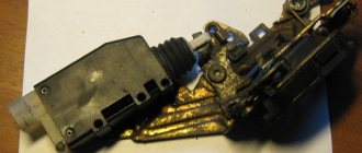
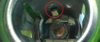
A story about how I repaired the Norma electrical package control unit. It all started with the fact that the driver's door electric lock stopped closing, I've already encountered this more than once, the teeth in the drive itself were cut off. I drove like this for two weeks, closing the driver's door with the key. But at one point, all the locks stopped closing, either from the alarm or from manually pressing the button in the driver's door. I replaced the drive with a new one, but that didn't help. 1. I tried to retrain the key fob again, it has not responded to pressing the buttons on the key fob for a long time. The training was successful, the key fob began to respond to button presses, and the car was set to normal security. But the door locks did not respond to closing. 2. I got to block 1118-6512010 “Norma”, I saw an unpleasant thing, the alarm installers assembled everything by twisting, without soldering. The wires for opening and closing the doors, from the alarm system, are connected to the second and seventh contacts of the block; they were soldered directly to the board, but quite efficiently; two holes for the wires were broken out in the case. Contacts from the ISO connector are suitable for this connector for connecting music in the car.
3. I cut off wires No. 2 and No. 7 from the “Nor”, nothing has changed, the drives are silent, inside the “Norma” you can hear the relays clicking. 4. No voltage is supplied to pin 14, 17, 18. 5. I disassembled the “Norma”, removed all the relays from the board, checked them, they all turned out to be working. 6. When you press the door lock button, ground appears along the blue wire (Contact No. 4). 7. I applied power directly from the battery to contacts 14 and 17 - all the doors except the driver's door closed, I also applied to 14 and 18, the driver's door closed, i.e. Drive wiring is correct. All the manipulations performed showed that some SMD components on the board had failed, I examined the board under a magnifying glass and did not find anything burnt out. 8. I went shopping for the “Norma” block, found it only at the car market, the stores in our small town of Sepversk didn’t have it, one store offered to deliver it to order in two weeks. It cost me quite a budget - 2000 rubles. In the store I came across two types of “Norma” 1118-6512010 and 1118-6512010-01, I took the one I had without the “-01” at the end, does anyone know what the difference is between them? 9. I left the store, immediately picked up the block, closed the door with the key, all the locks worked as expected, first they all opened, then they all closed. That is, the block is working and my wiring, as I said, is also all working. 10. I tried to close it using my own key fob, but there was no reaction. I retrained the key, now this manipulation took place at the level of automation, although at first I forgot to unhook the end on the diagnostic connector leading to BC STATE Matrix (this is very important as they write on the Internet). After training, the key fob worked as normal, opening and closing the doors.
11. I pulled out two contacts from the ISO connector (for connecting musical equipment), inserted them into contacts 2 and 7, and soldered the “green-white” and “blue-white” alarms to them. As I understand it, the impulse to “Norma” is supplied with negative polarity, so the “blue-red” and “green-red” wires are screwed to ground. I closed the doors with the signal, everything worked as expected.
While I was fiddling with “Norma” I re-read a bunch of all sorts of material, I realized that it is not so difficult to replace the key in the immobilizer bypass with a simple chip, otherwise you have to carry a red (training) key there. To retrain the key, I had to remove the dashboard and climb into the immobilizer bypass.
Double-glazed window control unit “Norma” 1118 – 6512010 for VAZ 11183 “Kalina”
©Aktuator On cars of the Kalina family, 2 types of non-interchangeable (by wiring) glass control controller 1118 - 6512010 and 11180 - 3763040 can be installed. 1118 – 6512010 has one 25-pin connection connector, 1118 – 3763040 (1118 – 3763040 – 10) – two connectors.
Remote control system for double-glazed windows “norm” on a VAZ 11183, Kalina. Controls power windows and central door locking. When the connector is removed, the engine does not start; the device performs some of the anti-theft functions.
Connection
* A regular shock sensor from any alarm system (Alligator, Saturn, Clifford, APS) is suitable.
+ 12 V connect to pin 12; body – on the 6th; We connect the signal wire (a ground appears on it at the moment of activity) to the 1st contact.
During normal arming, Kalina now reacts to an impact on the body (it sounds a horn and blinks turn signals). Similarly, instead of a shock sensor, you can connect a volume sensor (for example, single-level MMS‑1).
You can also connect a pager: + 12 V of the pager transmitter on pin 12, minus on pin 21.
Double-glazed window control unit 1118 – 3763040 (- 10 ) for VAZ 11183 “Kalina”
| Appearance | Controller board | Reverse side |
Double-glazed window control unit 2170 – 3763040 for VAZ 2170 “Priora”
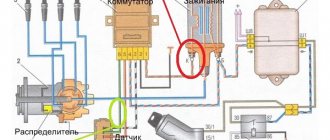
1 . 1 Malfunction in the VZ communication coil circuit
1 . 2 Malfunction in the circuit from the block to the communication coil to the APS ECU
1 . 3 Transponder missing in OK
1 . 4 The transponder in OK is faulty (detected during pre-production preparation)
1 . 5 The transponder in the Republic of Kazakhstan is faulty (detected during pre-production preparation)
1 . 6 Malfunction of the input transponder circuit in the APS ECU
1 . 8 The communication coil came off from the VZ pad on the inside
2. 2 Malfunction of W‑Line circuits in the APS or ICS units
2. 3 Lack of supply voltage on the APS or KSUD unit
2. 4 The “Normal” electrical package is faulty (the control driver has burned out)
2. 5 KSUD does not contact
Abbreviations: IS – status indicator; VZ – ignition switch; OK – training key; RK – working key; RC – remote control; KSUD – engine control system controller; ECU - electronic control unit
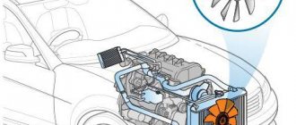
Malfunction of the central locking system in the Chevrolet Niva is considered a fairly common problem, even after the 2010 restyling, when more reliable components began to be used. On new Chevrolet Niva cars, as a rule, central locking with a key or alarm key fob does not work. The doors have to be opened manually. You can fix the malfunction on your own, the main thing is to determine the cause of the breakdown and know the location of the relays and mechanisms.
Resynchronization of remote control codes
In cases where the remote control buttons are pressed outside the range of the radio channel, the “floating” code counter in the remote control goes out of synchronization with the counter in the system control unit. If the number of button presses outside the signal reception area of the system exceeds 1000, the system stops responding to remote control commands. In this case, the remote control training procedure should be repeated.
Updated August 01, 2013
Due to the increasing number of cases of lost training (master) keys for car owners of Kalina, Priora, Grant, Niva-Chevrolet, we are introducing a new type of service: registration of working keys in these cars, without a master key!
Usually in such cases, it is necessary to change a set of blocks: ECU (electronic engine control unit), APS unit, glass control unit, ignition switch complete with door cylinders and new keys, etc.
Now in our company you can register a working key with buttons without a training key, and for an additional fee you can receive a new training (red) key for your car. For this procedure, you need to come by car and leave it while the work is being carried out. The work includes dismantling the necessary units (ECU, APS, etc.) from the car, programmatically changing data, installing units on the car and registering keys. We emphasize that a key registered in this way will cost more than registering a remote control yourself if you have a training key, but naturally cheaper than buying and replacing a set of blocks with new ones.
Update January 05, 2014
Attention! It is now possible to make a duplicate chip for autostart using a working key with remote control buttons! A master or training key is not required. The chip obtained in this way can be used both for installation in the immobilizer bypass unit to implement autostart, and for everyday use, starting the engine of Lada Kalina, Priora, Niva-Chevrolet cars. Such a duplicate is more expensive than a regular chip, which can be registered using a master key, but this is a real solution in cases where the master (training) key is lost. To create a duplicate, you need a car, a working key with remote control buttons (and it doesn’t even matter if it is partially faulty, for example, the buttons don’t work, etc., the main thing is that the ignition key starts the engine). The entire copying procedure takes 10-15 minutes. Contact us by phone in contacts.
Causes of central locking malfunctions
Most often, the electrical part of the solenoids control fails, and the locks themselves are considered relatively reliable.
The central locking of a Chevy Niva car works on the following principle: the signal for opening or closing the doors is transmitted by pressing a button on the key or turning the cylinder in the driver's door, while the signal passes through the central locking control unit and the on-board computer.
This scheme has its weaknesses, and the main reasons for failure are the following factors:
- short circuit in the circuit and fuse failure;
- chafing of wiring in flexible corrugation, loss of contact at joints due to vibrations and moisture ingress;
- central locking relay malfunction;
- error in the central locking control unit;
- lock motor failure.
Advice! If the car has an alarm system, the central locking may not open due to a malfunction of the alarm system. Perhaps the reason lies in the dead battery of the alarm control panel.
Car alarm connection points for Chevrolet Niva 2021, immo number 1118-6512010
Bypass immo on the steering column: white wire into the gap to the lineman.
All limit switches are on the immobilizer block.
The central locking unit does not have to be disassembled and soldered in there. Everything works perfectly according to the Priora scheme: a thin blue wire to the gap (the gap is closed, it is to ground - open).
Turns – blue and blue/black. Can be found in the gray connector, under the mounting block.
Monitoring engine operation (+) – one wire comes out of the generator very conveniently. We take it from him.
The handbrake is torn off and connected via a diode, otherwise it won’t work.
Keep in mind that removing the dashboard requires 4 self-tapping screws, but in the center of the panel it is so tightly latched that it is only possible to break this fastening bracket. Or install the whitefish behind the mounting block.
Articles on the topic
Alarm installation cards for Chevrolet Niva
“>
Operating principle and central locking diagram
Central locking has been installed on the VAZ 2123 since 2004. Since then, the Chevy Niva central locking scheme has not changed fundamentally and is installed on cars starting with the “Norma” configuration. To control the remote door opening, a remote control (remote control with a flip key) is used. It combines the functions of an immobilizer, ignition key, and door key. The signal from the remote control is received by the electrical package control unit (1118-6512010), which is responsible for opening the doors.
Pressing a button on the remote control opens or closes all car doors, including the trunk door. In the same way, the central locking is triggered when the key in the driver's door is turned half a turn to the right or left.
The operation of the electrical network is controlled by a standard relay type 90.3747, a 20 A fuse, limit switches in each door, and gear motors on the lock mechanisms.
A special feature of the Chevrolet Niva Central Locker is the ability to manually open and close the doors, even with the battery removed.
Important! The gearmotors are equipped with protection against overheating and turn off for a while after repeated activation of the central locking system.
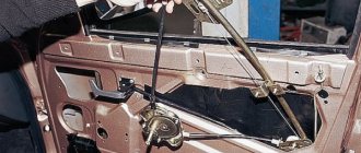
Door pinout for first generation Kalina
In all versions of the first generation Lada Kalina, the cable routing is the same.
Driver's door
- Output to the rear harness.
- A bundle of wires for connecting the speaker.
- Locking device.
- Driver's door control switch pinout element.
- Voltage to switch harnesses.
- Connection of the harness line to the mounting unit.
- Same as 5.
- Same as 6.
- Window regulator.
For front passenger
- Exit to the stern beam.
- Output to the appropriate speaker.
- Door lock drive.
- Electric window lift key.
- Power window control unit terminal harness.
- To the switch key of the corresponding node.
- Gearbox of the above device.
Rear doors
On the rear doors, the terminals are similar for both sides. Only two terminals are used here, where the first serves to connect to the rear electrical harness. The second is designed to supply an impulse and power to lock the doors.
Typical Lada Kalina pinout intended for the rear wiring harness
- Output to the rear door harness behind the driver.
- Voltage and indication of the rear left optical element.
- Same as 1 for the opposite side.
- Terminal for handbrake output.
- Kalina instrument pinout line.
- Output to the driver's door.
- Same as 5.
- Car interior lighting lamps.
- To the left turn signal.
- Connecting the fuel pump.
- Reverse transmission lock switch.
- Continuation of the highway from the front passenger door.
- Line articulation to the rear right speaker.
- Illumination lamp for the interior of the cargo compartment.
- Auxiliary stop.
- Alarm control unit.
- Same as 13 for the opposite side.
- Rear right turn.
- Output to rear optics located on the left side of the car.
- Output to cargo compartment wiring elements.
- Heated rear windshield.
Instrument panel pinout Kalina first generation
The decoupling is considered the most complex element of a car's electrical circuit. Here there are outputs from all important elements and assemblies of the machine:
- 1-5 – outputs responsible for connecting the front beam indication;
- 2.8 – similar for the stern;
- 6,7,9,10 – continuation of lines to the mounting unit and fuse-links;
- 11 – control lines for side, head and interior lights;
- 12 – combination instrument panel;
- 13 – keys for adjusting the heater cooler positions;
- 14 – for powering the air supply box;
- 15 – factory anti-theft element – ignition unit;
- 16 – immobilizer switch;
- 17 – part of the Kalina instrument panel pinout, responsible for indicating and supplying current to the ECM;
- 18 – onboard cigarette lighter;
- 19 – emergency warning button;
- 20 – brake light button located on the pedal;
- 21 – indicator on the windshield wiper system;
- 22 – rear window heating switch;
- 23 – power supply unit for turn signals and low/far modes of head optics;
- 24 – wiper control lever;
- 25 – horn button;
- 26 – supply voltage to the light bulb in the glove compartment;
- 27 – similarly, for the on/off key;
- 28-29 – pinout for Kalina radio – standard position:
- 30 – voltage to the heater cooler motor;
- 31 – resistor network of the above element;
- 32 – main pinout of Kalina EUR;
- 33 – lighting of the ventilation channel and stove.
Ways to solve problems with central locking Niva Chevrolet
Before starting work, it is recommended to evaluate your repair skills and experience with electrical wiring in a car. Special equipment may be required, and at a minimum, a tester is required to diagnose electrical circuits. Troubleshooting always starts from simple to complex.
Fuse failure
Most often, the cause of its burnout is a short circuit or overload in the circuit. In the mounting block of cars manufactured before 2009, it is designated F6; on cars after 2010, it is located under the number F10.
Gearmotors
Their breakdown does not occur often, but repairing or replacing motors in doors requires partial disassembly of the door and removal of the upholstery. A faulty motor can be detected by the silence on its part when the central locking system is activated or incorrect operation (does not open completely, fires every other time, extraneous sounds).
Functionality is checked with a multimeter or by connecting to the battery directly. Replace the gearmotors with a new assembly if the old one cannot be repaired.
Advice! It happens that the sounds of the motor operating are heard, but the door does not respond to signals from the key. In this case, it is necessary to check the rods coming from the locks to the gearmotors and door handles.
Wiring
In addition to the central locking system, alarm wires, limit switches, audio systems, and power windows enter the door. Despite the rational S-shaped bend of the door wiring in the corrugation, damage to one or more wires occurs. The second weak point is the contacts inside the door.
The integrity of the wiring is checked by “ringing” suspicious sections of the circuit. The found break is cleaned and connected by soldering or crimping bushings. Replacing a broken wire entirely with a new one is not always advisable due to the complexity of the work.
Relay circuit
Power to the central locking can be supplied through the main relay used for low beam headlights and interior lighting. There are also schemes with a separate relay for the central locking, which is installed next to the control unit of the door opening system.
Central locking control unit
This block is present only on cars with the “Norma” configuration and higher. A common reason for its failure is a short circuit in the circuit or large voltage surges, leading to melting of the microcircuit contacts. Diagnosed visually (traces of melting on the body) or with an electrical tester.
The central locking unit, as a rule, is not repaired and is simply replaced with a new one.
On-board computer (ECU)
On Chevy Niva, the central locking scheme on later cars involves the participation of the on-board computer in the processes of opening and closing doors, as well as setting the alarm. Such a scheme allows you to expand the functionality of the central locking system, connect an alarm system with auto start and make the operation of the car more comfortable.
Information about errors and malfunctions of the central locking is obtained through a scanner or PC, which is connected to the car via a standard OBD2 connector. Errors in the computer are one of the reasons why remote opening does not work. In the application you can reset errors and find out the cause of the problem. In difficult cases, the control unit is reflashed.
Main block with fuses and relays
This block is located to the left of the steering column and is closed from below with a lid. To get to it, you need to tighten 2 screws, then press the top edge of the cover and gradually free it from all fasteners.
p, blockquote 3,0,0,0,0 –>
p, blockquote 4,0,0,0,0 –>
The block that appears will be held on a special bracket. The fuse diagram itself and the number of elements on it may vary depending on the configuration and year of manufacture.
For cars manufactured before 2009
Scheme - option 1
Scheme - option 2
p, blockquote 6,0,0,0,0 –>
p, blockquote 7,0,0,0,0 –>
Explanation of fuses
p, blockquote 8,0,0,0,0 –>
F1 (5 A) - license plate lamps, instrument panel lamps, indicator light on the dashboard, engine compartment lamp, additional brake light lamp, left side lamps.
p, blockquote 9,0,0,0,0 –>
If any of the listed lamps do not work, check this fuse and the lamps themselves, their connectors and wiring.
p, blockquote 10,0,0,0,0 –>
F3 (10 A) - high beam in the left headlight, indicator lamp for turning on the high beam headlights on the dashboard . Similar to relay K5.
p, blockquote 11,0,0,0,0 –>
F4 (10 A) - backup fuse.
p, blockquote 12,0,0,0,0 –>
F5 (30 A) - front door electric windows and their relays . If, when operating the power window, the window goes down but not up (or vice versa), check the button on the door. When lowering and raising, the polarity and direction of rotation of the motor are different. It could also be a problem with the window lift mechanism. To get to it, you need to remove the door trim. Check that the mechanism does not bite anywhere and that the gears are intact, without broken teeth. If there are problems, you can replace the entire power window drive with a new one.
p, blockquote 13,0,1,0,0 –>
F6 (15 A) - door lock control unit . If one or more doors stop opening, check this fuse. The issue may be in the central locking, control unit, as well as the mechanisms themselves, rods and door locks. If you have no experience, it is better to contact a car service.
p, blockquote 14,0,0,0,0 –>
F7 (20 A) - sound signal and its relay, cigarette lighter . If the horn does not work, check this fuse, the steering column contacts and the wiring; the contacts may have oxidized and the wiring may have become frayed. Also check the horn itself, you can replace it with another one, for example, a two-tone one from Volga. If the cigarette lighter does not work, check the wiring and its contacts. The white wire is responsible for the backlight, the red and black wires go to the cigarette lighter contacts. Do not insert non-standard connectors into the cigarette lighter, they may cause a short circuit. If the connector in the cigarette lighter moves to the sides, it is better to use a splitter and insert this connector there.
p, blockquote 15,0,0,0,0 –>
F8 (20 A) - rear window heating element and relay (contacts) . Similar to relay K7.
p, blockquote 16,0,0,0,0 –>
F9 (20 A) - rear window heating relay coil, additional relay, rear window wiper motor, wiper and washer switch.
p, blockquote 17,0,0,0,0 –>
F10 (20 A) - backup fuse.
p, blockquote 18,0,0,0,0 –>
We combine two different alarms
So, let's say that one alarm system in the Niva-Chevrolet is already installed (from the factory). This means that we will use the wires connected to its module initially. There are limit switch taps and ground, as well as central locking control wires.
The cable we are talking about is a power cable and is usually covered with yellow insulation.
Additional alarm connection diagram
To control all locks, and not just the driver’s actuator, you need to implement the following connection option:
Let's list the features of this option:
- The relay contacts built into the main unit are connected to the breaks in the signal wires (see figure);
- The normally open contact of the locking relay is left free. In “Shnivy”, closure occurs when the cord is “in the air”;
- The duration of the control pulse is set to “0.8 seconds”;
- The control output is programmed to be activated during unlocking. This output controls another, third relay.
Let's talk about why an additional relay is needed here. If we remove it, we will see that the passenger locks cannot be opened from the key fob. In principle, this option is also acceptable: except for remote unlocking of three doors, everything will work.
The 15 Amp fuse shown in the diagram is in series with the cable leading to the actuators.
Connecting without using a fuse is strictly prohibited. At the same time, it is not necessary to protect the relay windings with a pre-flask. The same applies to the signal wires, that is, to the normally open contact of the unlocking relay. In principle, fuses can be added to all three circuits. And also, the winding of the “lower” relay can be powered from the 87th contact.
Practical implementation of the scheme
Surely the reader knows where the fuse box is installed in the Niva-Chevrolet. This block must be dismantled by unscrewing one screw from the top.
A plastic box will be secured under the indicated block. She is exactly what we need.
There are three “important” cords on the connector of the module shown here: blue, blue-yellow, yellow. Taps from the three break points are extended to the installed signaling, as well as to an additional relay (see diagram). Particular attention should be paid to the connections of power wires.
You can make an additional relay module yourself. A current not exceeding 8 Amperes will flow through the contacts here, so there will be no difficulties:
The diode shown in the main diagram can be anything (its characteristics are not so important). The main thing is that it is there, otherwise you can burn out the control output to which the switched winding is connected.
Remember the main thing: you can carry out any installation work only when the negative terminal is disconnected from the battery.
It is better to connect power cables by twisting, but knowing how to do it correctly is an entire art. All connection points must be isolated. But this will not be enough: in places where the metal touches, the cord is protected with heat-resistant insulation. This is how you can protect yourself from unforeseen consequences.
Features of programming the new signaling
Let's say the scheme discussed above was implemented without errors. At the second step, as you might guess, you need to correctly program the alarm. Otherwise, there is a possibility of burning out the actuators installed in the passenger doors. The advice is simple: you cannot make a control pulse longer than one second. However, the default value is 0.7 or 0.8.
The signal output used must also be programmed correctly (it must be activated at the moment of unlocking). An alternative method is to use the 2-step unlock output. The pulse duration on it must be set within 0.7-0.8 s. The default value is 30 s, and guess what this means in this case.
Some versions of the Niva-Chevrolet are equipped with central locking. If there really is a standard central locking system, it is controlled by a single module. It should be noted that this same module acts as a standard signaling device. It turns out that an alarm system with central locking is installed in the Shniva from the factory, but you can always connect an additional alarm to it, that is, to the standard module. One of the options for such a connection is discussed further.
Cigarette lighter fuse
If the cigarette lighter does not work, then the first thing you should check is the socket itself for the presence of foreign objects and the integrity of the fusible link, which opens the circuit if the reverse mechanism of the cigarette lighter spiral does not work.
p, blockquote 46,0,0,0,0 –>
p, blockquote 47,0,0,0,0 –>
Next, check the fuse on the unit itself. On the diagrams it is marked as number 6 (F6).
p, blockquote 49,0,0,0,0 –>
If this does not help, then the question remains with the electrical wiring itself.
p, blockquote 50,0,0,0,0 –>
In this video you can clearly see an example of how to get to the fuse box and replace them.
p, blockquote 51,0,0,0,0 –>
You should also check the supply voltage to the connectors with the electric motor wires, as breaks occur in these circuits. To determine the lack of contact, you need to ring each wire with a multimeter. The drive motor is checked with a measuring device; to do this, it is necessary to measure the resistance of its windings.
Niva Chevrolet repair manual. Diagram of the door lock system: 1 – mounting block; 2 –…
If clicks are not heard, check that there is power at the switches. Conclusions Determining the causes of a central locking malfunction is quite simple.
The rest of the peeps act on their own, each opening its own door. Sometimes installing an alarm yourself can lead to blocking failure, so you should entrust this work to specialists.
Depending on the method of switching on the relay, the polarity of the voltage changes, ensuring a corresponding change in the position of the lock latch.
Some models may be equipped with an anti-theft system built into the central locking system. If you are unable to independently determine the cause of the failure by performing a series of general checks, contact your Chrysler dealer for advice.
With the engine off, switch the door lock switches in both directions Open - Closed. The relay should make clearly audible clicks.
Door lock relay location. There are a lot of different things to do, it’s cold outside, the toad was choking me to change it at the service station, and somehow I drove like that, locking it with the key. And then last week the door completely stopped working, neither opening nor closing.
When using the original signaling, only the starboard turn signals blinked. I read on the Internet that the electrical package located behind the fuse box burns out.
It cost me quite a budget in rubles. I came across two types of “Norma” in the store and, I took the one I had without the “” at the end, does anyone know what the difference is between them?
I left the store, immediately picked up the block, closed the door with the key, all the locks worked as expected, first they all opened, then they all closed. That is, the block is working and my wiring, as I said, is also all working.
We combine two different alarms
So, let's say that one alarm system in the Niva-Chevrolet is already installed (from the factory). This means that we will use the wires connected to its module initially. There are limit switch taps and ground, as well as central locking control wires.
The lock is controlled by two wires - yellow-blue and blue. In addition, you will need to find another cord that powers the passenger door actuators.
The cable we are talking about is a power cable and is usually covered with yellow insulation.
Additional alarm connection diagram
To control all locks, and not just the driver’s actuator, you need to implement the following connection option:
Let's list the features of this option:
- The relay contacts built into the main unit are connected to the breaks in the signal wires (see figure);
- The normally open contact of the locking relay is left free. In “Shnivy”, closure occurs when the cord is “in the air”;
- The duration of the control pulse is set to “0.8 seconds”;
- The control output is programmed to be activated during unlocking. This output controls another, third relay.
Let's talk about why an additional relay is needed here. If we remove it, we will see that the passenger locks cannot be opened from the key fob. In principle, this option is also acceptable: except for remote unlocking of three doors, everything will work.
The 15 Amp fuse shown in the diagram is in series with the cable leading to the actuators.
Connecting without using a fuse is strictly prohibited. At the same time, it is not necessary to protect the relay windings with a pre-flask. The same applies to the signal wires, that is, to the normally open contact of the unlocking relay. In principle, fuses can be added to all three circuits. And also, the winding of the “lower” relay can be powered from the 87th contact.
Practical implementation of the scheme
Surely the reader knows where the fuse box is installed in the Niva-Chevrolet. This block must be dismantled by unscrewing one screw from the top.
A plastic box will be secured under the indicated block. She is exactly what we need.
There are three “important” cords on the connector of the module shown here: blue, blue-yellow, yellow. Taps from the three break points are extended to the installed signaling, as well as to an additional relay (see diagram). Particular attention should be paid to the connections of power wires.
You can make an additional relay module yourself. A current not exceeding 8 Amperes will flow through the contacts here, so there will be no difficulties:
The diode shown in the main diagram can be anything (its characteristics are not so important). The main thing is that it is there, otherwise you can burn out the control output to which the switched winding is connected.
Remember the main thing: you can carry out any installation work only when the negative terminal is disconnected from the battery.
It is better to connect power cables by twisting, but knowing how to do it correctly is an entire art. All connection points must be isolated. But this will not be enough: in places where the metal touches, the cord is protected with heat-resistant insulation. This is how you can protect yourself from unforeseen consequences.
Features of programming the new signaling
Let's say the scheme discussed above was implemented without errors. At the second step, as you might guess, you need to correctly program the alarm. Otherwise, there is a possibility of burning out the actuators installed in the passenger doors. The advice is simple: you cannot make a control pulse longer than one second. However, the default value is 0.7 or 0.8.
The signal output used must also be programmed correctly (it must be activated at the moment of unlocking). An alternative method is to use the 2-step unlock output. The pulse duration on it must be set within 0.7-0.8 s. The default value is 30 s, and guess what this means in this case.
Basket
Double-glazed window control unit “Norma” 1118 – 6512010 for VAZ 11183 “Kalina”
Remote control system for double-glazed windows “norm” on a VAZ 11183, Kalina. Controls power windows and central door locking. When the connector is removed, the engine does not start; the device performs some of the anti-theft functions.
Connection
* A regular shock sensor from any alarm system (Alligator, Saturn, Clifford, APS) is suitable.
+ 12 V connect to pin 12; body – on the 6th; We connect the signal wire (a ground appears on it at the moment of activity) to the 1st contact.
During normal arming, Kalina now reacts to an impact on the body (it sounds a horn and blinks turn signals). Similarly, instead of a shock sensor, you can connect a volume sensor (for example, single-level MMS‑1).
You can also connect a pager: + 12 V of the pager transmitter on pin 12, minus on pin 21.
Double-glazed window control unit 1118 – 3763040 (- 10 ) for VAZ 11183 “Kalina”
1 . 1 Malfunction in the VZ communication coil circuit
1 . 2 Malfunction in the circuit from the block to the communication coil to the APS ECU
1 . 3 Transponder missing in OK
1 . 4 The transponder in OK is faulty (detected during pre-production preparation)
1 . 5 The transponder in the Republic of Kazakhstan is faulty (detected during pre-production preparation)
1 . 6 Malfunction of the input transponder circuit in the APS ECU
1 . 8 The communication coil came off from the VZ pad on the inside
2. 2 Malfunction of W‑Line circuits in the APS or ICS units
2. 3 Lack of supply voltage on the APS or KSUD unit
2. 4 The “Normal” electrical package is faulty (the control driver has burned out)
2. 5 KSUD does not contact
Abbreviations: IS – status indicator; VZ – ignition switch; OK – training key; RK – working key; RC – remote control; KSUD – engine control system controller; ECU - electronic control unit
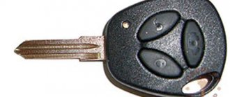
The remote control key looks like this:
IMPORTANT ANNOUNCEMENT.
General diagram of electrical equipment of Kalina
On the electrical circuit of the Lada Kalina model, the pinout of connectors is carried out in several stages. According to the factory drawings, the general position of the elements is initially revealed, then each node is deciphered separately.
- Right front headlight assembly.
- Sensor indicating the position of the hood lock.
- Powering the horn.
- Starter terminal block.
- Battery power cables.
- Generator working unit.
- Voltage supply terminal for the wiper drive.
- Left head optics contact block.
- Right door lift chip.
- Likewise for the glass lift gearbox.
- Output to driver's door speaker.
- Driver's door lock drive.
- Windshield washer reservoir motor.
- Overboard temperature meter sensor output.
- Standard ECM connection connector.
- Same as 12 for the front passenger.
- Indicator of the remaining brake fluid in the expansion tank of the system.
- Same as 11 for the front passenger.
- The front passenger door power window switch, located in the driver's control unit.
- Driver's door window lift key.
- Lock button.
- Power supply for the lift gearbox for the front passenger door.
- Input of the mounting assembly.
- Anti-theft control unit.
- Likewise for signaling.
- Pinout on the dashboard.
- Right turn.
- Glove compartment lighting.
- Glove box light switch.
- Stop key switch.
- Anti-theft ignition switch terminal.
- Headlight design.
- Supply current to the steering column lever connector.
- Left turn signal.
- Right rear speaker block.
- Rear right door electric lock drive.
- Window window heating unit.
- Reverse blocking.
- Hazard breaker.
- Adjusting the stove fan.
- Auxiliary resistor for the stove.
- Stove motor.
- Power supply for rear left speaker.
- Rear left door lock terminal.
- Power supply for fuel pump and float.
- White reverse lamp switch.
- Stop button.
- Cigarette lighter power supply.
- ZX blocking – solenoid power supply.
- Chips for a tape recorder or speaker system.
- Illumination of used ventilation and stove.
- Supplying voltage and signals to the EUR.
- Interior lighting lamps.
- Rear right lampshade.
- Power to the trunk lid lock.
- Cargo compartment lighting drive.
- State license plate illumination.
- Auxiliary stop lamp.
- Directly heated windshield.
- Cargo compartment illumination lamp.
- Left stern light.
The following is the pinout of the first generation Kalina wires for each section individually. This was done due to the increased complexity of the main circuit, where all elements of the on-board circuits are indicated at once. An inexperienced user will not be able to navigate the generalized instructions.
Purpose:
The remote control is designed for remote control of locking and unlocking of car doors, turning on and off super-locking doors, turning on and off the alarm system, raising the windows, controlling the locking of the tailgate (trunk lid), and also as a coded electronic key for the APS-6 immobilizer
The remote control is mounted on the blade of the ignition switch key type 1118-3704010 and is designed to operate:
- with electrical package control unit 1118-6512010
- with driver's door module 1118-3763080, 2170-3763080-00/10
2) via transponder channel:
- with immobilizer control unit APS-6 2123-3840010-ХХ;
- with immobilizer control unit APS-6.1 1118-3840010-ХХ;
- with electrical package controller-2170-3763040.
Electrical package remote control system “Norma”
On vehicles with trim levels 55 and 34, the Norma electrical package remote control system (SDUEP) is installed.
SDUEP “Norma” is intended for:
- remote locking/unlocking of door locks with simultaneous activation/deactivation of the vehicle security mode;
- locking all doors by turning the key in the driver's door lock;
- locking/unlocking all doors with a button on the driver's door;
- activation of an alarm system in case of violation of vehicle security zones;
- turn off the alarm remotely or after turning on the ignition with your key.
SDUEP “Norma” consists of an electrical package control unit 1, fig. 7-52, and the remote control (RC), fig. 7-49.
The connection diagram of the SDUEP “Norma” is shown in Fig. 7-50. The addresses of the output plugs of the “Norma” electrical package control unit are given in Table 7-16.
Rice. 7-49. Remote control:
1 — remote control; 2 — door lock button; 3 — door unlock button.
Training procedure:
Carrying out the training procedure leads to the following consequences:
- the engine control controller activates the anti-theft function if it has not been activated;
- the system changes its password to a new one chosen at random;
- a new system password is written into the training key;
- all remote controls that were previously trained are erased from memory;
- The codes of those remote control units that were trained in this training procedure are stored in memory.
The training procedure is applied in the following cases:
- activating the anti-theft function in the controller (for example, in a new car or replacing a faulty controller);
- erasing old and training new remote controls if lost;
- changing the system password if the owner admits that his system password may have been read (for example, when selling a car from one owner to another)
- remote control training when replacing a faulty immobilizer with a new one.
Please note: Due to the importance of the training key, it is not recommended to use it for everyday use and should be kept in a safe place.
Key programming instructions for Lada Kalina, Priora, Granta, etc.
- Close all doors. Turn on the ignition with the training key and wait in the on state for at least 6 seconds.
- Turn off the ignition. The indicator light in the warning lamp unit should flash quickly (at a frequency of 5 times per second) while the learning procedure is being carried out correctly. If the lamp stops flashing quickly, it indicates an incorrect operation, an out-of-time interval, or a malfunction. Remove the training key from the ignition switch.
- While the warning lamp is flashing (about 6 seconds), insert the remote control and turn on the ignition. The immobilizer buzzer should emit three beeps. If the buzzer does not sound and the indicator has stopped flashing, this means: - the time interval of 6 seconds has been exceeded and it is necessary to repeat the learning procedure, starting from step 1; -immobilizer is faulty
- Wait 6 seconds for the buzzer to emit two more beeps and turn off the ignition.
- If it is necessary to train the second remote control, then you should perform steps 3...4 again, using the second learning remote control to turn on the ignition. If not, continue from step 6.
- After turning off the ignition for no more than 6 seconds, while the indicator is flashing, remove the remote control, insert the learning key and turn on the ignition. The buzzer should beep three times. Wait 6 seconds until the buzzer beeps two more times.
- Turn off the ignition without removing the training key, wait 6 seconds until the buzzer sounds a single sound signal. The indicator should flash twice as fast. If the sound signal does not sound and the flashing indicator stops, you should return to step 1 and repeat the learning procedure. If a repeated failure occurs when performing step 7, this means that the ECM was previously trained with a different key, in which case the controller should be replaced.
- After the buzzer gives a single sound signal, no later than 3 seconds, turn on the ignition for 2...3 seconds and then turn it off (after turning on the ignition, the buzzer will sound three times and the indicator will stop flashing). The hazard warning lights should flash and the car horn should beep.
- Remove the learning key. Wait with the ignition off for at least 10 seconds. Insert the working key and turn on the ignition. Wait 6 seconds, if the indicator does not flash, test start the engine, the engine should start. If the indicator flashes, turn off the ignition and wait at least 10 seconds. Turn on the ignition. The warning light should not flash and the engine should start. If, after turning on the ignition, after 6 seconds the indicator lights up with a constant light, then the learning procedure must be repeated, starting from step 1.
Replacing the remote control battery
The remote control is equipped with a CR2032 lithium battery, the initial supply voltage of which is 3 V. If the remote control supply voltage is within normal limits, then each time you press any button on the remote control, the indicator lights up with a short flash. If, when you press any button on the remote control, the indicator lights up with two short flashes or does not light up at all, then you should replace the battery with a new one.
To do this, you need to unscrew the screw from the side of the case opposite the control buttons, separate the halves of the case, remove the board from the case, replace the battery with a new one, observing the polarity; insert the board into the case; snap the housing halves together and tighten the screw.