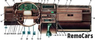
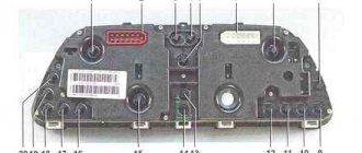
Designation of icons on the dashboard of the VAZ 2115
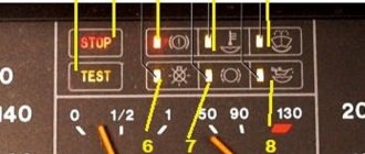
The following describes the warning lights and panel indications, which are indicated and numbered in the photo above.
| Number in order | Decoding |
| 3/4 | Turn signal indicators. They light up at the same time when the alarm is activated. |
| 7 | Minimum fuel level light. Lights up when the gas tank is empty. |
| 8 | Indicator for turning on external lighting. |
| 9 | The brake system is faulty. The brake fluid level and pad wear should be checked. |
| 10 | The high beam headlights are activated. |
| 12/15 | Information displays, basic information about the daily time and mileage is displayed here. |
| 13 | Emergency light activation key. |
| 14 | Check engine light. If it lights up, further movement is not recommended. |
| 16 | The battery is low. The operation of the generator should be checked. |
| 17 | The indication indicates that the handbrake lever is raised. |
| 18 | The warning light means that the engine oil pressure has dropped below normal. |
| 19 | This indicator is used exclusively on carburetor cars. The light indicates that the throttle valve is in the open position. |
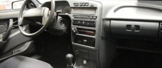
Dashboard
The location of the vehicle controls complies with UNECE standards and regulations.
For ease of use, handles, buttons, switches and control devices located on the instrument panel are marked with functional symbols. The following controls are located on the instrument panel (Fig. 1.7). 1 – lever for switching direction indicators and headlights. 2 – front door glass blower nozzle. 3 – instrument cluster. 4 – steering wheel. 5 – sound signal switch.
6 – alarm switch. Pressing the button turns on the flashing light of all direction indicators and the warning lamp in the instrument cluster. Pressing the button again turns off the alarm:
7 – ignition switch (lock) (Fig. 1.8), combined with an anti-theft device, is located on the right side of the steering column. The key in the lock can be in one of three positions:
0 – “off”. All consumers are turned off, the key is removed. When the key is removed, the locking mechanism of the anti-theft device is activated. To ensure that the steering shaft is locked, turn the steering wheel to the right or left until it clicks. To turn off the anti-theft device, you need to insert the key into the ignition switch and, turning the steering wheel slightly left and right, turn the key to position “I”; I – “ignition”. The ignition is on, the key is not removed, the steering is unlocked; II – “starter”. The key cannot be removed and the steering is unlocked. This is achieved by turning the key clockwise to overcome the spring force. In this position, the key is not fixed; for the starter to operate, it must be held by hand. The ignition switch is equipped with a starter lock when the engine is running. To re-engage the starter after an unsuccessful start attempt, move the key from position “I” to position “0”, and then again to position “II”.
8 – switch lever for windshield wipers and washer.
9 – the immobilizer warning sensor is installed on a vehicle with a fuel injection system, equipped with an electronic anti-theft system, and is designed to transmit a secret code from the working code key through the immobilizer unit to the engine control controller.
10 – block of signal lamps of the on-board control system. The following lamps are installed in the block (Fig. 1.9):
1 – warning lamp for an emergency drop in the oil level in the engine crankcase. Lights up orange if the oil level in the engine crankcase has dropped below the “MIN” mark of the indicator;
2 – warning light for insufficient liquid level in the windshield washer reservoir. Lights up orange if there is less than 1 liter of washer fluid left in the tank;
3 – warning light of insufficient coolant level in the expansion tank. Lights up orange when the coolant level on a cold engine drops below the permissible limit;
4 – warning light for open doors. Lights up red when the car door is not closed;
5 – warning lamp for malfunction of the brake light lamp or side lights. Lights up red if there is a malfunction of the brake light lamp when you press the brake pedal or any side light lamp when it is turned on;
6 – warning lamp for wear of the front brake pads. Lights up orange when you press the brake pedal and stays on until the ignition is turned off if the thickness of the front brake pads has decreased to 1.5 mm;
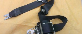
7 – warning light for unfastened seat belts. Lights up red if the driver's seat belts are not fastened.
11 – external lighting switch
. The switch block contains two mechanically connected switches: – side light switch 1. By successively pressing the switch key, the side lights in the headlights and rear lights are turned on and off; when the side lights are on, the control lamp with a green filter lights up in the button; – headlight switch 2. When you press the switch button (fixed position), the headlights turn on. When you press the button again, the headlights turn off.
12 – block of key switches includes the following
: – switch 1 of the front fog lights. The fog lights are turned on by pressing the switch button while the side light switch button is pressed, and at the same time the indicator lamp in the button lights up. When you press the button again, the fog lights turn off; – switch for 2 rear fog lights. When you press the switch button, the rear fog lights turn on if the exterior lighting is on. When you press the button again, the rear fog lights turn off; – switch 3 for heating the rear door glass. When you press the switch button, the glass heating is turned on, and at the same time the indicator lamp in the button lights up. When you press the button again, the heating turns off.
13 – trip computer
, installed on some of the cars produced, is designed to measure, accumulate and display on a digital display one of the following parameters: – current fuel consumption; – average total fuel consumption; – average speed; – distance traveled; – current time; – travel time.
15 – warning lamp for anti-lock braking system (ABS). Installed instead of a plug if the car is equipped with an anti-lock braking system.
16 – airbag status indicator lamp. Installed instead of a plug if the car is equipped with an airbag.
17 – central nozzles of the ventilation and heating system.
18 – cover of the upper glove box. To access the upper storage compartment with the lower storage compartment cover folded down, press the upper cover lock lever.
19 – side nozzle of the interior ventilation and heating system.
20 – cover of the lower glove box. To open it, press the lock handle against the handle. When the exterior lighting is turned on, a special flashlight illuminates the inside of the glove compartment.
21 – magazine shelf.
22 – control panel for the ventilation and heating system.
23 – socket for radio equipment. The installation of radio equipment is provided, corresponding in size and method of fastening to international standards.
24 – front ashtray.
25 – right front seat heating switch.
26 – left front seat heating switch.
27 – parking brake lever. To brake the car with the parking brake, lift lever 2 all the way up - the red warning lamp in the instrument cluster will light up. To release the brakes of the car, pull the lever up a little, press button 1 at the end of the lever handle and lower it all the way down - the warning light should go out.
28 – gear shift lever.
29 – cigarette lighter. To use the cigarette lighter, press the socket until it locks and release. After approximately 20 seconds, the cartridge automatically returns to its original position, ready for use.
30 – heater electric fan switch.
31 – accelerator pedal.
32 – brake pedal.
33 – clutch pedal.
34 – handle for adjusting the steering column angle.
35 – instrument panel lighting switch. Rotate the handle to adjust the brightness of the instrument lighting and switch backlights if the outdoor lighting is turned on.
36 – control knob for hydraulic headlight adjustment. Rotate the knob to adjust the angle of the headlight beam so as to prevent dazzling oncoming drivers. The hydraulic corrector handle positions correspond to the following vehicle loading options:
0 – one driver; 1 – all seats are occupied; 2 – all seats are occupied and cargo is in the luggage compartment; 3 – one driver and cargo in the luggage compartment.
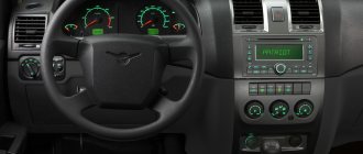
Tidy 2115: description and purpose of buttons and knobs
If everything is simple with the levers on the steering rack, there is a headlight position switch and a turn signal switch on the left. Buttons are more difficult.
On the dashboard, the main keys are placed in a separate “strip”. To understand the essence, we present their decoding from left to right.
- Switch for outside parking lights.
- Activation of low beam headlights.
- Front fog lights.
- Rear PTFs. If not installed, reserve.
- Rear window heating button.
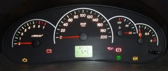
Lada 2115: the oil light on the center panel is on
If an icon in the shape of a watering can appears on the console, this indicates that there are problems in the engine lubrication system. This is caused by a drop in the oil level in the crankcase or a pump malfunction. If the engine is old, the problem may be caused by clogged oil lines.
What does the exclamation mark on the Lada 2115 tidy mean?
On the "tag" the symbol is used in only one form - a red indicator in a circle. The icon indicates a malfunction in the vehicle's brake system. If this symbol lights up while driving, stop and find the cause of the breakdown. Usually it is enough to add fluid to the expansion tank or replace worn pads.
The battery light on the dash is on 2115
A red battery icon indicates that the battery is not charging properly. A complete diagnosis of on-board systems associated with the generator set and its wiring is required.
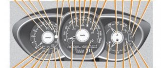
VAZ-2115 dashboard diagram
The controls of the VAZ-2115 passenger car are located in accordance with the UNECE norms and regulations. For greater ease of use of handles, buttons, switches and control devices located on the dashboard, they have graphic symbols indicating their functional purpose.
Rice. 1.1 Instrument panel of the VAZ-2115 (diagram).
How to check for errors on the device
The manufacturer has provided the ability for the driver to independently read faults without the presence of additional equipment.
To perform a self-diagnosis, you will need to follow a procedure.
- Sit in the driver's seat, insert the ignition key and press and hold the daily mileage reset button.
- Next, turn the ignition key in the lock, but do not start the engine.
- Release the reset button. Now the on-board computer self-diagnosis process will begin. This is accompanied by the inclusion of all lights and devices.
- Quickly press the mileage reset button again - this will display the version of the software used on the screen under the speedometer.
- If you press the button again, error codes will be displayed on the same screen.
Removing the error from the device memory
This procedure is used in three cases:
- the occurrence of an error blocks the ability to operate the car (you need to get to the service station under your own power);
- a complete check of all components was carried out and no fault was found;
- The damaged part has been repaired or replaced.
To reset the on-board control system data, you must remove all terminals from the battery and then plug it back into the vehicle's power circuit. It will only take a few seconds to disconnect the battery. After this, the error record will be erased from the system memory. If you want to carry out this procedure for further operation of the vehicle, then remember that the trip should be short - to the nearest car service center.
The tidy and on-board computer 2115 do not work: reason
The engine may not start, but auxiliary devices such as power windows or wipers may work.
If this happens, you should check the points.
- Inspect all fuses for damage.
- Check the power supply terminals of the on-board computer and instrument panel. Often the terminals become loose or oxidize, which leads to similar troubles.
- If all the above-described elements are intact, you should remove the BC from the machine and check its functionality.
How to decipher codes
If you do not know what the data displayed on the display means, then it is pointless to independently check the functionality of the sensors. Therefore, it is important to know how to decipher combinations. The following numbers appear most frequently:
- If code 1 appears, then the fault lies in the microprocessor of the on-board unit itself. This error can be corrected by changing the computer software. It is important to use only official firmware, otherwise you will damage the entire electrical system of the car.
- If the malfunction is hidden in the incorrect operation of the fuel sensor, then 2 will appear on the display. The same number means problems with the electrical wiring, especially if it is displayed in addition to 8.
- When the voltage in the network is high, error 4 appears, and when voltage is low, error 8 appears. If you notice these data, then you need to check the generator and battery. VAZ-2115 owners most often encounter generator malfunctions. It will need to be repaired or completely replaced.
- Malfunctions in the operation of the control lamp in the diagnostic circuit are displayed on the display in the form of a combination - 12.
- Failure of the oxygen level sensor is displayed as error 13. Check the filters, most often they are the cause of this combination. Combinations 33 and 34 indicate mass air flow. In this case, you may need to replace the sensor itself. A malfunction of the controller itself is indicated by code 61 displayed on the display. Experts recommend that if one of these combinations occurs, a full check of the functionality of the vehicle components is carried out. Start with the electrical wiring.
- Car enthusiasts often encounter combinations 14 and 15, which may appear along with an indicator indicating the need to add antifreeze. It is important to interpret this malfunction correctly - the appearance of this data on the display means that the temperature in the system is increased or decreased. The reason for this may be a malfunction of the thermostat. If the node is not damaged, then the problem most likely lies in the control unit.
- Combinations 16 and 17 are output when the voltage in the on-board network is insufficient or too high. It is necessary to check all wiring for short circuits and breaks.
- Code 19 occurs if the crankshaft position sensor does not respond correctly to the test. In this case, it is necessary to check the vehicle with an external device. If it shows a combination in the range from P0340 to P0343, then the breakdown may be hidden in the controller itself.
- With error 24, the on-board computer stopped receiving data about the vehicle speed.
We recommend: Car diagnostics using a laptop: how to do it yourself?
Description of faults
Once you understand the self-diagnosis modes, think about the errors encountered during diagnostics.
| Serial number | Decoding |
| 1 | There are problems with the ECU. |
| 2 | The fuel level sensor is providing incorrect data. |
| 4/8 | There are problems with the machine's power supply. |
| 12 | The error lamp circuit is faulty. |
| 13 | Lambda probe – power supply circuit open. |
| 14/15 | Temperature sensor incorrect signal. |
| 16/17 | There is a short circuit in the on-board network. |
| 19 | DPKV incorrect data. At the same time, the car often does not start. |
| 21/22 | Typical TPS errors. Cleaning the damper is usually sufficient. |
| 23/25 | The intake air temperature meter has failed or is stuck. |
| 24 | Speed sensor is broken. |
| 27/28 | DC is faulty. |
| 33/34 | The air flow meter is not working properly. |
| 35 | The idle speed control sensor is faulty. |
| 42 | The ignition system circuits are broken or not working correctly. |
| 43 | The knock sensor is damaged. |
| 44/45 | The composition of the fuel mixture is incorrect. |
| 51/52 | ECU memory module errors, |
| 53 | CO2 setting sensor error. |
| 54 | The octane corrector is faulty. |
| 55 | The composition of the fuel mixture is incorrect. |
| 61 | The oxygen sensor has failed. |
Tidy 2115 stopped working
Occurs after power surges or moisture getting under the panel (condensation). If the device has completely failed, but other elements of the car are working, check the fuse and wiring of the element.
When only part of the panel does not show or the board lighting has failed, perform diagnostics of the illuminators and their contact groups.
Tidy does not light up
If the backlight does not function, as well as the dimensions on the left side of the car, check the corresponding fuse. When the insert is working properly, you will need to diagnose the mounting block for voltage.
Panel 2115 blinks
It happens when the device does not work correctly. The backlight blinks and the elements constantly jump. There are problems with contacts here. The pads may become loose or oxidized.
The solution to the problem is to clean the contacts from oxidation and tighten/replace the pads.
The temperature sensor on the device 2115 does not work
The pointer indicator is a reliable element of the system. But various problems may arise here. Usually trouble is caused by factors.
- Sensor stuck in one position.
- Damage to wiring.
- The motor of the device itself is damaged.
- Problems with the electronic board or ECU.
The solution lies in diagnosing the system and correcting breakdowns.
The arrows on the dashboard 2115 do not work
The fault lies with the blown fuse F3. Before replacing it, be sure to diagnose the wiring and eliminate problems and possible short circuits.
Possible faults
The instrument cluster of the VAZ 2115, like any other component of the car, is a device susceptible to various malfunctions.
In this case, there are not so many of them and they are all connected with the electrical part:
- If the instrument panel does not work, there may be several reasons. Either this is poor contact between the device and the ECU, which can be solved by replacing the plug or cleaning the contacts, or a malfunction of the control panel itself, or “glitches” in the operation of the control unit. Typically, the device’s inoperability appears after the PCB has been dismantled and installed in place. In this case, the reason, most likely, is a poor connection of the contacts, so all connectors need to be reconnected, taking into account the pinout.
- Some devices do not work - tachometer, speedometer, fuel level controller. The problem can be either electrical and consist of poor contact, or mechanical (breakage of the speed sensor, fuel level in the gas tank, etc.). Usually replacing the regulators will solve the problem.
- The backlight of the VAZ 2115 instrument panel does not work. If all the bulbs immediately refuse to work, the reason, again, needs to be looked for in the electrical part - maybe a wire has simply come loose somewhere. If only one or several lamps have burned out, then they simply need to be replaced (a video about the installation of a tuned device in a dozen VAZs was made by Pavel Ksenon).