The content of the article:
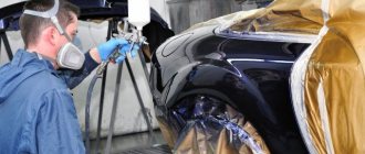
- Rear suspension device of VAZ-2106
- How a faulty suspension affects the movement of the car
- Diagnostics of springs and shock absorbers
- Checking the condition of rubber parts
- Replacing shock absorbers
- Replacing springs
The VAZ-2106 car has more than 40 years of history. It began production in 1976 and was finally removed from the production line in 2006. Throughout this period, its rear suspension existed in its original version. This was due to the simplicity and reliability of the design, as well as its maintainability.
More than 10 years after the end of production, the “six” can be found on the roads. Until now, it remains the “softest” car. Partly thanks to its rear suspension.
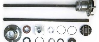
Replacing the rear beam of Lada 2106 (VAZ 2106)
If, when starting your “six” from a stop or driving on an uneven road, knocking noises are heard from the rear axle, and the rear of the car moves to the side on potholes, then most likely the rear suspension of the VAZ 2106 requires repair.
Most often, the rubber bushings of the reaction rods or transverse rods are to blame for the loss of vehicle stability on the road. Less commonly, the cause of unstable behavior on the road is faulty shock absorbers and springs.
The price of “classic” rear suspension elements is low, and replacing them is not difficult.
Diagnostics of springs and shock absorbers
The main part of the VAZ 2106 rear suspension failures can be identified during a trip. However, faults must be confirmed using diagnostic methods.
Diagnostics begins with an external inspection of the car on a level surface. First of all, you need to pay attention to the springs. If they sag, then the vehicle's ground clearance will be lower than required.
To make an initial conclusion about the condition of the shock absorbers, you should press on the rear wing in the area of the wheel. The body weight is enough for the car to sag under its weight. If the shock absorbers are working, then the car will swing once, and the vibration will immediately stop. Otherwise, the rocking will continue. Shock absorbers often fail due to oil leaks. Worn oil seals lead to oil smudges becoming visible on the outer surface.
Preparatory work
Before removing the beam, it is necessary to remove the shock absorbers and suspension springs. For this operation, in addition to standard keys and heads, you will need a pry bar, a jack and spring ties.
The order of operation is as follows:
- Drive the car into the pit, put the handbrake on, and install wheel chocks under the rear wheels.
- Loosen the upper nuts of the front shock absorbers located in the engine compartment (to prevent the shock absorber rod from turning, it should be held with an open-end wrench).
- Unscrew the top nuts and remove them along with the washers and springs (the location of the elements must be remembered, this will be useful during assembly).
- Unscrew the nuts securing the shock absorbers to the lower arms.
- Pull out the shock absorbers.
- Loosen the front wheel mounting bolts.
- Raise the car on a jack, place the front part of the car on supports, remove the front wheels (special supports or ordinary bricks are located under the side members at the point where they connect to the body).
Further actions are performed sequentially for the right and left levers:
- Unscrew the nuts securing the lever two turns (otherwise it will be difficult to lift it with a jack).
- Raise the end of the lever with a jack and remove the stabilizer rubber bracket by unscrewing the fastening nuts.
- Partially unscrew the nuts securing the lower ball joint and knock it out of the knuckle with a hammer (it is better to use a special puller instead of a hammer).
- Move the stabilizer through the top pin using a pry bar.
- Lower the lever and remove the jack.
- Lift the upper arm and pull out the suspension spring, prying it up with a pry bar from below.
Reinstalling the parts is done in the reverse order. Before installing the springs, they should be compressed with ties.
Replacing springs
To change the rear suspension springs of a VAZ 2106, you need the rear axle to be in a suspended state. You can do this one by one, lifting the car on a jack, or you can do it simultaneously, on a lift.
Hanging is necessary in order to maximize the space between the bridge and the body. This makes it easier to remove and insert the spring. The wheel must first be removed. The stroke of the shock absorber is less than the length of the spring, so to remove it, you need special pullers. They are installed on the sides of the spring symmetrically and tighten it.
The upper part of the spring is in contact with the body through a rubber gasket. It has a groove into which the top turn fits exactly. Therefore, when reinstalling, you must ensure that the shape of the gasket matches the coil.
Repair work on the rear suspension of the VAZ 2106 is very simple. You just have to be consistent and be careful.
Source
Beam dismantling
The VAZ 2107 beam serves as the basis for attaching the lower suspension arms, so before removing it, the arms must be unscrewed. To dismantle the lever, simply unscrew the two nuts securing the lever axis to the beam.
The car engine is also attached to the beam. Before removing the beam, it is necessary to secure it to the hoist using the eye on the cylinder head located between the carburetor and the tee. Before hooking the engine onto the hoist, it is necessary to remove the air filter so as not to damage it. Once the engine is suspended, you can begin to remove the beam.
Unscrew the nuts securing the engine mounts to the beam.
Support the beam so that it remains in place after unscrewing from the side members. To do this, you can use a stack of boards, placing them under the part.
Unscrew the beam fastening bolts running in the horizontal plane, then the nuts of the bolts running vertically.
Raise the front of the car, controlling the beam so that it does not fall from the supports.
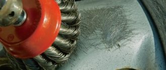
Repair without welding
Thresholds 2106 are very rarely repaired without welding. This is due to the fact that the “youngest” car is 13 years old, such a service life for metal is critical. If necessary, you can patch corrosion holes with metal patch or use epoxy resin, putty or fiberglass. Necessary tools that will be needed for repair:
- sandpaper R-80;
- fiberglass cover;
- epoxy resin;
- rubber spatula, roller (optional);
- solvent;
- rust remover;
- automotive putty;
- aluminum powder;
- primer;
- enamel.
Repair with epoxy resin and fiberglass goes through the following stages:
- Clean the area of corrosion with sandpaper and rust remover until bare metal.
- Prepare epoxy resin, be sure to add aluminum powder to the mixture, this will reduce the fragility of the material after drying.
- Degrease the defect on the threshold.
- Apply a thin layer of glue to the surface and cover the damage with a piece of fiberglass. Cut the patch larger than the damaged area.
- If necessary, apply several layers of fiberglass, coating each layer with epoxy resin.
- Roll each layer with a roller to remove excess air.
Epoxy glue dries for at least 12 hours at an air temperature of 20 degrees; if the repair is carried out in a damp garage, it will take at least 24 hours to dry.
If it is necessary to update the body after winter, then the repair procedure is similar; if there is no corrosion, the surface is cleaned, primed, and painted.
Process technology
The VAZ 2106 body is straightened immediately before painting the restored part:
- The surface to be treated is cleaned of dirt, washed, dried and degreased. Remove old paint from the working surface.
- Use frequent gentle blows of a hammer to smooth out the dent. If the defect is deep, then the process is performed from the edge of the damage, and gradually moves towards its center. Metal substrates are placed on the reverse side of the area to be restored. They must have the appropriate shape.
- Metal breaks are repaired using a welding machine. Next, the weld is ground.
- The area restored from damage is covered with putty. It levels the work surface.
- The putty part is sanded and painted.
The putty should be applied in a thin layer. Otherwise, the paint will become covered with numerous cracks and begin to fall off.
Rear axle VAZ 2106. Device. Gear ratio
The standard structure of the rear axle, which is equipped with the VAZ 2106, consists of a traverse and a gearbox. It is to the first that the latter is attached. It contains the main gear, which has a drive pair of gears, as well as a differential.
Rear axle VAZ 2106. Diagram
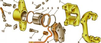
Explanation of the VAZ 2106 rear axle diagram:
- Wheel brake drum mounting bolt;
- Guide pin;
- Axle bearing oil deflector;
- Brake drum;
- Cast iron brake drum ring;
- Rear axle wheel cylinder;
- Fitting for bleeding the brake drive;
- Axle bearing;
- Bearing lock ring;
- Rear axle beam flange;
- Axle shaft seal;
- Suspension spring support cup;
- Rear axle beam;
- Upper suspension rod mounting bracket;
- axle guide;
- Differential bearing nut;
- Differential box bearing;
- Differential box bearing cover;
- Breather;
- Differential satellite;
- Main drive driven gear;
- Left axle shaft;
- Axle gear;
- Rear axle gear housing;
- Drive gear adjusting ring;
- Bearing spacer;
- Drive gear bearing;
- Drive gear oil seal;
- Oil seal deflector;
- Flange-fork universal joint;
- Screw;
- Oil deflector;
- Main gear drive gear;
- Axle of satellites;
- Axle gear support washer;
- Differential box;
- Right axle shaft;
- Brackets for fastening suspension parts;
- Axle bearing thrust plate;
- Rear brake shield;
- Rear brake pad;
- Friction lining;
- Axle shaft flange.
Malfunctions of the rear axle gearbox:
- during its operation, loud noises are heard;
- the external temperature regime of the housing increases;
- This part is constantly jamming.
In these cases, it is recommended to completely replace the components and checking the oil fluid level is indispensable. That is, you will need to buy an oil seal, bearings, and an axle shaft. However, you can immediately purchase a used rear axle.
At the same time, despite the strength characteristics of the fastening, it, due to its design features, does not have a complex structure. Therefore, even a driver who has minimal knowledge of locksmithing can handle it.
Video review on how to determine what is buzzing:
In some cases, repair work is carried out. Here, experienced mechanics must take into account one nuance - the gear ratio. Size is also of great importance. The key factor is the cost of repairs.
The gear ratio is the ratio of the number of teeth of the driven gear and the drive gear, one of the main parameters of any transmission.
The gear ratios of the VAZ classics vary and are equal:
- 3.9 — gear ratio in the “six” VAZ 2106;
- 4.1 - in the “troika” VAZ 2103;
- 4.3 - in the “kopeck” VAZ 2101.
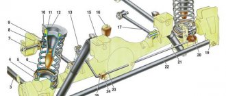
The rear suspension structure is shown in Fig. 4-30.
Removing and installing suspension
Withdrawal. Raise the rear of the car and install stands. Remove the rear wheels. Disconnect the driveshaft from the drive gear flange.
Disconnect the hydraulic brake hose from the steel tube installed on the bridge and take measures to prevent fluid leakage from the brake system.
Rice. 4-30. Rear suspension: 1 — spacer sleeve; 2- rubber bushing; 3 — lower longitudinal rod; 4 — lower insulating gasket of the spring; 5 — lower spring support cup; 6 — compression stroke buffer; 7 — bolt for fastening the upper longitudinal rod; 5 - bracket for fastening the upper longitudinal rod; 9 — suspension spring; 10 - upper spring cup; 11 — upper insulating gasket of the spring; 12 — spring support cup; 13 — rod of the rear brake pressure regulator drive lever; 14 — rubber bushing of the shock absorber eye; 15 — shock absorber mounting bracket; 16 — additional compression progress buffer; 17-upper longitudinal rod; 18 — bracket for fastening the lower longitudinal rod; 19 — bracket securing the transverse rod to the body; 20 — rear brake pressure regulator; 21 — shock absorber; 22 — transverse rod; 23 — pressure regulator drive lever; 24 — holder of the lever support sleeve; 25-bearing lever bushing; 26- washer; 27 - spacer sleeve.
Disconnect the rear parking brake cable bracket from the body, remove the front cable release spring and, by unscrewing the locknut and adjusting nut, release the rear cable branch. Disconnect the rear brake pressure regulator drive rod from the bracket on the bridge beam. Disconnect the upper ends of the shock absorbers.
Place a hydraulic jack under the rear axle beam. Disconnect the longitudinal and transverse rods from the brackets on the body, lower the jack and remove the axle.
Start disassembling the suspension:
— remove the shock absorbers from the brackets on the bridge beam;
— disconnect the longitudinal and transverse rods from the brackets on the bridge beam.
Rear suspension parts are shown in Fig. 4-31.
Installation of the rear suspension is carried out in the reverse order of removal.
In this case, install class A springs (with yellow markings) on the suspension. In exceptional cases, when there are no springs of this class, the installation of springs of class B (with green markings) is allowed.
Rice. 4-31. Rear suspension parts: 1 — lower longitudinal rod; 2- rubber bushing; 3 — bracket for fastening the lower longitudinal rod to the body; 4 — spacer sleeve; 5 — upper longitudinal rod; 6 - additional compression progress buffer; 7-spring; 8 — upper spring cup; 9- compression stroke buffer; 10-upper spring insulating gasket; 11 — shock absorber; 12 — lower insulating gasket of the spring; 13 - transverse rod.
To prevent damage and excessive tightening of the elastic bushings of the rod hinges and shock absorbers: ; — load the rear of the car so that the distance from the axle beam to the body spar, measured 100 mm from the crossbar bracket (Fig. 4-32), is 125 mm\; — use a torque wrench to tighten the nuts on the bolts securing the longitudinal and transverse rods, as well as on the pins securing the shock absorbers to the bridge beam and to the body.
Checking technical condition
Before checking, wash all parts thoroughly. When washing, protect rubber parts, bushings and protective coatings from solvents. It is best to wash parts in an ultrasonic bath using Favorit Ultra detergent.
Rice. 4-32. Rear suspension installation diagram: 1-body spar; 2 — bracket for the transverse rod; 3 — rear axle beam; X-125mm
Springs
Check the elastic characteristics of the springs at the control points (Fig. 4-33), after compressing them three times until the coils touch.
Rice. 4-33. Basic data for checking the rear suspension spring.
Note. According to their length under a load of 2950 R (305 kgf), springs are divided into two classes. Class A - length greater than 273 mm and class B - length less than 273 mm. Class A springs are marked with yellow paint on the outside of the coils, and class B springs are marked with green paint.
Check if the spring is deformed. If the spring elasticity does not correspond to the data in Fig. 4-33 or deformation may cause the spring to malfunction, replace it.
Check the condition of the rubber spring support pads; if necessary, replace them with new ones.
Barbells. Check:
— whether the rods are deformed; if possible, straighten them;
— are there any cracks on the brackets of the rear axle beam and the body; if cracks are found, repair the brackets;
— condition of the elastic bushings of the rod hinges; if necessary, replace them with new ones using the tool kit 67.7820.9517.
Read interesting articles about the VAZ2106 car...
Fastening the beam to a VAZ 2107
The front beam of the VAZ 2107, due to its transverse location in the engine compartment, is also called a “cross member”. The car engine and lower suspension arms are attached to it. If the beam has fatigue cracks, damage, or is deformed in such a way that it allows the required wheel alignment angles to be set, it needs to be replaced. This is a very labor-intensive procedure that requires dismantling, subsequent installation and adjustment of front suspension parts. During the operation, the engine must be suspended on a traverse or hoists. It is better to carry out the work with a partner, and the replacement should be done in a pit or a lift.
Preparatory work
Before removing the beam, it is necessary to remove the shock absorbers and suspension springs. For this operation, in addition to standard keys and heads, you will need a pry bar, a jack and spring ties.
The order of operation is as follows:
- Drive the car into the pit, put the handbrake on, and install wheel chocks under the rear wheels.
- Loosen the upper nuts of the front shock absorbers located in the engine compartment (to prevent the shock absorber rod from turning, it should be held with an open-end wrench).
- Unscrew the top nuts and remove them along with the washers and springs (the location of the elements must be remembered, this will be useful during assembly).
- Unscrew the nuts securing the shock absorbers to the lower arms.
- Pull out the shock absorbers.
- Loosen the front wheel mounting bolts.
- Raise the car on a jack, place the front part of the car on supports, remove the front wheels (special supports or ordinary bricks are located under the side members at the point where they connect to the body).
Further actions are performed sequentially for the right and left levers:
- Unscrew the nuts securing the lever two turns (otherwise it will be difficult to lift it with a jack).
- Raise the end of the lever with a jack and remove the stabilizer rubber bracket by unscrewing the fastening nuts.
- Partially unscrew the nuts securing the lower ball joint and knock it out of the knuckle with a hammer (it is better to use a special puller instead of a hammer).
- Move the stabilizer through the top pin using a pry bar.
- Lower the lever and remove the jack.
- Lift the upper arm and pull out the suspension spring, prying it up with a pry bar from below.
Reinstalling the parts is done in the reverse order. Before installing the springs, they should be compressed with ties.
Beam dismantling
The VAZ 2107 beam serves as the basis for attaching the lower suspension arms, so before removing it, the arms must be unscrewed. To dismantle the lever, simply unscrew the two nuts securing the lever axis to the beam.
The car engine is also attached to the beam. Before removing the beam, it is necessary to secure it to the hoist using the eye on the cylinder head located between the carburetor and the tee. Before hooking the engine onto the hoist, it is necessary to remove the air filter so as not to damage it. Once the engine is suspended, you can begin to remove the beam.
Unscrew the nuts securing the engine mounts to the beam.
Support the beam so that it remains in place after unscrewing from the side members. To do this, you can use a stack of boards, placing them under the part.
Unscrew the beam fastening bolts running in the horizontal plane, then the nuts of the bolts running vertically.
Raise the front of the car, controlling the beam so that it does not fall from the supports.
Beam installation and suspension assembly
The new VAZ 2107 beam is installed in the reverse order of removal. When installing the engine on the beam, it is necessary to control the location of the pillow pins so that they fit into the mounting holes.
If there are no spring ties, they can be replaced with a jack and wire. To do this, you need a screw jack, used on Zhiguli and Muscovites, and steel wire. It is worth noting that this operation is very risky - if the wire breaks, the spring can “shoot”. The procedure itself looks like this:
- Raise the jack bar up so that a spring can be inserted between it and the base.
- Using two or three wire loops, tighten the spring to the jack so that it does not bend in an arc or jump out during compression.
- Compress the spring, gradually lowering the jack bar.
- Secure the spring with wire twists in a compressed state.
- Extreme caution must be used when using this method.
- If possible, be sure to use a specialized spring tie and not a jack.
- The spring must be compressed enough so that it can be easily installed, but no more. Otherwise, problems will arise when removing twisted wires.
After installing the spring in place, the wire twists must be removed using pliers. They should be removed carefully and evenly so that the spring does not bend, but falls into place.
If you find an error, please select a piece of text and press Ctrl+Enter.
Replacement of rear suspension parts of VAZ 2106 Zhiguli
- Repair manuals
- Repair manual for VAZ 2106 (Zhiguli) 1976-2005.
- Replacement of rear suspension parts
13.2.1 Replacing rear suspension parts EXECUTION ORDER It is more convenient to perform the work on a lift.
To replace the shock absorber, hang the wheel and support the rear axle beam with a stand so that the shock absorber is slightly compressed. Using two 19mm wrenches, unscrew the self-locking nut securing the lower shock absorber eye. … 13.2.2 Replacing rear shock absorbers PERFORMANCE ORDER It is more convenient to perform the work on a lift. To replace the shock absorber, hang the wheel and support the rear axle beam with a stand so that the shock absorber is slightly compressed. Using two 19mm wrenches, unscrew the self-locking nut securing the lower shock absorber eye. ...
13.2.3 Replacing rear suspension springs PERFORMANCE ORDER Disconnect the shock absorber from the rear axle beam bracket and... ...tighten the spring with two special ties (see Appendices). Instead of zip ties, you can use two or three strong staples, which are inserted from two opposite sides into a spring, compressed by the weight of the car...
13.2.4 Removing and replacing rear suspension parts EXECUTION ORDER Place a hydraulic jack under the rear axle beam. We sequentially remove and replace with new (repaired) rear suspension parts. Using two “19” keys, unscrew the fastening of the lower (long) longitudinal rods. With two keys “at 19” the door...
13.2.5 Replacing the rod bushings PERFORMANCE ORDER If the rear suspension rod bushings are worn out, you can install new rods with the bushings pressed in at the factory. However, the bushings can be replaced yourself using a special tool or as shown below. We knock out or press out the steel spacer sleeve from the hinge...
↓ Comments ↓
1. General information
1.0 General information 1.1 Safety precautions
2. Diagnosis of faults
2.0 Diagnostics of faults 2.1 diagnostics of faults in the engine and its systems 2.2 Diagnostics of faults in the clutch 2.3 diagnostics of faults in the gearbox 2.4 Diagnostics of faults in the driveline, rear axle, chassis, steering and braking system 2.5 Diagnosis of faults in the body 2.6. Diagnosis of electrical equipment faults
3. Engine
3.0 Engine 3.1 Cylinder head and timing mechanism 3.2 Lubrication system 3.3 Oil change 3.4 Replacing the camshaft drive chain guide 3.5 Replacing the camshaft and valve levers 3.6 Replacing the valve stem seals 3.7 Replacing the intake and exhaust manifold gaskets 3.8 Replacing the cylinder head gasket ov 3.9 Disassembling the head cylinder block, valve grinding
4. Engine power system
4.0 Engine power system 4.1 Replacing the air filter element 4.2 Replacing the fuel pump 4.3 Repairing the fuel pump 4.4 Replacing the fuel tank and its hatch cover
5. Carburetor
5.0 General information about the carburetor 5.1 Cleaning the fuel filter 5.2 Replacing the idle air system solenoid valve 5.3. Adjusting the carburetor 5.4 Replacing the carburetor 5.5. Carburetor repair
6. Engine cooling system
6.0 Engine cooling system 6.1 Replacing the coolant 6.2 Replacing the coolant pump 6.3. Replacing the thermostat 6.4 Replacing the engine radiator
7. Exhaust system
7.0 Exhaust system 7.1 Replacing exhaust system parts
8. Clutch
8.0 Clutch 8.1 Replacing fluid and bleeding the clutch hydraulic drive 8.2 Adjusting the drive 8.3 Replacing the clutch master cylinder 8.4 Repairing the clutch master cylinder 8.5 Replacing the clutch slave cylinder 8.6 Replacing the pressure plate assembly and clutch release bearing
9. Gearbox
9.0 Gearbox 9.1 Checking the level and changing the oil in the gearbox 9.2 Replacing the reverse light switch 9.3 Replacing the secondary shaft cuff 9.4 Replacing the gearbox 9.5 Repairing the gearbox 9.6 Replacing the speedometer drive 9.7 Features of repairing a five-speed gearbox
10. Cardan transmission
10.0 Cardan transmission 10.1. Maintenance 10.2. Replacing the driveshaft
11. Rear axle
11.0 Rear axle 11.1 Checking the serviceability of the rear axle 11.2 Changing the oil 11.3 Replacing the axle shaft and its cuff 11.4 Removing and installing the rear axle 11.5 Replacing the cuff of the drive gear 11.6 Replacing the gearbox 11.7 Repairing the gearbox
12. Front suspension
12.0 Front suspension 12.1. Maintenance 12.2 Replacing the bearings and hub cuff 12.3 Replacing the cushions and stabilizer bar 12.4 Replacing the ball joints 12.5 Replacing the shock absorbers 12.6 Replacing the springs 12.7 Replacing the upper arms and their rubber-metal hinges 12.8 Replacing the rubber-metal joints of the lower arms on a car 12.9 Replacing the lower arms 12.12 . Adjusting wheel alignment angles
13. Rear suspension
13.0 Rear suspension 13.1 Checking technical condition 13.2. Replacement of rear suspension parts
14. Steering
14.0 Steering 14.1 Adding oil 14.2 Checking the condition of the steering 14.3 Adjusting the gear engagement 14.4 Replacing steering rods 14.5 Replacing and repairing the pendulum arm 14.6 Removing and installing the steering wheel 14.7 Removing and installing the steering shaft 14.8 Removing and installing the steering mechanism 14.9 Removing the bipod
15. Brake system
15.0 Brake system 15.1 Checking the condition of the hydraulic drive 15.2 Checking the vacuum brake booster 15.3 Checking the functionality of the pressure regulator 15.4 Replacing brake fluid and bleeding the brake system 15.5 Replacing the brake pads of the front wheels 15.6 Replacing the brake pads of the rear wheels 15.7 Replacing the brake caliper of the front wheel 15.8 Replacing the brake cylinders of the front wheels 15 .9 Repair of front wheel brake cylinders
16. General information
16.0 General information 16.1. Checking electrical circuits 16.2 Fuse blocks 16.3 Replacing fuses 16.4 Replacing the main and additional fuse blocks 16.5. Replacing the relay 16.6 Replacing the ignition switch 16.7 Replacing the contact part of the ignition switch 16.8 Battery 16.9. Generator 16.10. Starter 16.11. Ignition system 16.12. Lighting, light and sound alarms 16.13. Windshield cleaner and washer 16.14. Repair of the electric heater motor 16.15. Control devices
17. Body
17.0 Body 17.1 Replacing the front bumper 17.2 Replacing the radiator grille 17.3 Replacing the hood latch 17.4 Replacing the hood 17.5 Replacing the windshield 17.6 Replacing the interior rear view mirror 17.7 Replacing the sun visor 17.8 Replacing the headliner 17.9 Replacing the ceiling grab handle
18. Heating and ventilation system
18.0 Heating and ventilation system 18.1 Replacing the electric heater fan 18.2 Replacing the heater radiator 18.3 Replacing the radiator casing 18.4 Replacing the heater valve
19. Car body care
19.0 Car body care 19.1 Car washing 19.2 Preservation and protection of paintwork
20. Applications
20.0 Applications 20.1 Tools used in addition to the standard set 20.2 Electrical diagram of VAZ-2106, VAZ-21061, VAZ-21063 cars produced in 1976–1987. 20.4 Tightening torques for threaded connections 20.5 Basic data for adjustments and monitoring 20.6 Characteristics of spark plugs 20.7 Fuel, lubricants and operating fluids used 20.8 Lamps used on the vehicle 20.9 Lip seals (oil seals)