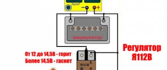
- diagnose the voltage regulator - the voltage measurement mode is set on the tester (measured at the battery terminals or at the terminals of the generator unit). During normal operation, the parameter should be in the range from 14 to 14.2 Volts, and when you press the gas, it should increase by no more than 0.5 Volts). In case of discrepancy, change the voltage relay;
diagnostics of the diode bridge of the generator - the tester is switched to sound mode, namely, when the probe outputs are shorted, a characteristic sound can be heard. You need to check each diode in different directions, but the sound should be audible in only one (the sound is heard in both directions - the diode is broken and must be replaced accordingly, and it is best to change the entire diode bridge);
The VAZ 2109 generator can be repaired either at a service station or independently. In a nutshell, the whole process consists of several stages: dismantling the generator, disassembling the generator, troubleshooting and replacing parts, assembling the generator unit, installing and connecting the generator device.
Tools required for repair work: a vice, a set of wrenches, a set of screwdrivers, a removable tool for bearing devices.
To disassemble the generator you will need:
- disconnect the battery by removing its terminals and de-energizing the on-board network;
- remove the cap from the terminal and unscrew the corresponding nut;
- Having removed the wiring from the stud, disconnect the block with the wiring going to the unit connector;
- having loosened the tightening of the assembly to the adjusting bar, lift the assembly up until it stops against the cylinder head;
- release the generator pulley from the belt;
- Having unscrewed the screw securing the bar to the cylinder block, under the car, unscrew the screws of the bracket on the internal combustion engine;
- We dismantle the generator by removing it from the engine compartment;
- we disassemble the generator and replace failed elements;
- Assembly and installation should be done in reverse order.
Let's sum it up
Taking into account the above information, it becomes clear that timely noticed and identified breakdowns can not only avoid problems during vehicle operation, but also often increase the service life of the generator.
Design Features
VAZ 2109 cars can be equipped with two models of generator units. These are 37.3701 and 9402.3701.
Description of the structural elements of the first:
- 1 — clamping fitting;
- 2 - bushing;
- 3 - buffer fitting;
- 4 — rear cover of the unit;
- 5 - bolt fixing the rectifier device;
- 6 - the rectifier unit itself;
- 7 - valve of this device;
- 8 - capacitor component;
- 9 — rear bearing element of the rotor shaft;
- 10 — slip rings;
- 11 — pulley of the rotor device;
- 12 - brush connected to terminal B of the regulator;
- 13 — contact 30, necessary for connecting energy consumers;
- 14 — contact element 61 of the generating set;
- 15 - brush connected to output Ш on the control mechanism;
- 16 - contact B of this element;
- 17 — the voltage regulator itself in the on-board network;
- 18 — pin for fixing the generating set to the tension bar;
- 19 — impeller;
- 20 - shaft;
- 21 — washers for fixing the bearing device;
- 22 - thrust ring;
- 23 — front bearing element of the rotor device pulley;
- 24 — rotor winding;
- 25 - pole piece of this device;
- 26 - another winding;
- 27 — stator mechanism;
- 28 — front cover of the generator unit.
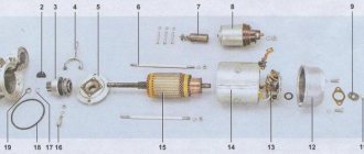
Diagram of device model 37.3701
Design of unit 9402.3701:
- 1 — protective casing of the device;
- 2 — contact B+ for connecting the electrical equipment of the machine;
- 3 - capacitor device;
- 4 - common contact of additional diode elements. It connects to the D+ output on the control fixture;
- 5 — fixing device for positive diodes of the rectifying mechanism;
- 6 — clamp for negative diode elements;
- 7 - positive diode;
- 8 - negative element;
- 9 — voltage regulator in the machine’s electrical network;
- 10 — rear cover of the generating set;
- 11 — coupling bolt;
- 12 — front cover of the generating set;
- 13 - stator winding;
- 14 - thrust ring;
- 15 — front bearing element of the rotor mechanism shaft;
- 16 - shaft;
- 17 - nut;
- 18 — shaft of the rotor mechanism;
- 19 — cone-shaped washer;
- 20 - regular washer;
- 21 — pole pieces of the rotor mechanism;
- 22 — core of the stator device;
- 23 - bushing;
- 24 — winding of the rotor mechanism;
- 25 — rear bearing element of the rotor pulley;
- 26 — bushing of the bearing element;
- 27 — slip rings;
- 28 — brush assembly holder;
- 29 — contacts of the stator mechanism winding;
- 30 - additional diode element;
- 31 - common contact D.
Design of the generator 9402.3701
Carburetor power units are equipped with devices model 37.3701, and injectors - 9402.3701. These units are similar in design; they are synchronous AC motors. They are equipped with a built-in rectifier unit based on silicon diode elements. And the voltage regulator in them is electronic.
On vehicles built before 1996, 37.3701 models used separate adjusters and brush holders. In such devices, the voltage from pin 30 was supplied to pin B. In later versions, this parameter is supplied to pin B, since B is absent.
Checking the rotor winding
A common problem with a car alternator is a short circuit in the windings. This can happen as a result of a sudden power surge, water ingress, worn brushes, etc. Since you can check the integrity of the alternator windings using a multimeter, only if you have full access to them will you need to dismantle the entire assembly. We will not describe this process as it differs from machine to machine. Before checking the removed alternator for the presence of rotor windings, it must, of course, be disassembled.
After removing the rotor, we find slip rings on its shaft. There are only two of them. Switching the multimeter to ohmmeter mode, connect its probes to these rings. The device should provide a resistance within 2-5 Ohms. These are normal values for a good rotor. Higher resistance indicates poor contact between the rings. Otherwise, an interturn short circuit is likely to occur when the instrument readings are close to zero.
How to check for serviceability?
Before diagnosing problems with injection and carburetor cars, you must start the engine and let it run for a few minutes. Then, pressing the gas pedal, you need to increase the number of crankshaft revolutions to 3 thousand/min.
To create a simulation of driving in normal mode, enable:
- driving lights;
- rear window heating systems;
- stoves.
Diagnostics with a multimeter:
- The tester is used to measure the voltage at the battery terminals. This parameter will be 13.2 volts in model 9402.3701 and 13.6 V for 37.3701. If, during diagnostics, without removing the voltage at the battery terminals, the obtained value turns out to be different, this indicates a break or short circuit in the windings of the device. The voltage regulator and brush assembly may also fail. Sometimes the problem is oxidation of the contact components of the field winding.
- To ensure that the regulatory mechanism is working, all energy consumers are switched off. Only the high beam optics remains switched on, after which the voltage measurement procedure is repeated. This parameter should be in the range from 13.2 to 14.7 volts for model 94.3701. In the 37.3701 electric generator, the resulting value will be from 13.6 to 14.6 V.
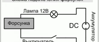
- If the control element on model 9402.3701 is removed, it can be checked by connecting a light source to the brush mechanism. In particular, between its elements. The lamp should be rated at 1-5 watts and 12 volts. The DC power supply is connected to the D+ pins and device ground. Diagnostics is performed first by activating the voltage at 12 volts, and then at 15-16 V.
- In the first case, the light source should work, but in the second, it should not. If it is activated when 12 and 15 volts are supplied, then a breakdown must be looked for in the regulatory device. If there is no combustion, the cause should be checked for a break or broken contact between the brush elements and the terminals of the device. The regulator itself is changed to restore the generator's functionality. To test the device 37.3701, the light bulb is connected to contacts B and C, this is a plus, as well as to ground.
- Checking the valves of the rectifier device is carried out by disconnecting the cables from the battery, generator unit, and also the regulator contact. The positive terminal from the battery is connected through a light source to the B+ output on the generator device 9402.3701. If this is model 37.3701, then it must be connected to output 30. The negative contact is ground, connected to the housing. If, as a result of the actions performed, the light source started working, then the problem is a short circuit (in both blocks).
- Diagnosis of a similar problem on positive valves is carried out by connecting the positive contact of the battery to the B+ output (for model 37.3701 - contact 30). The connection is made through the light source. The negative contact goes to the output of the phase winding of the stator mechanism (you can connect to any). The inoperability of one or more positive valves will be indicated by activation of the light bulb.
- The procedure for diagnosing a short circuit on the negative contacts of the element is performed by connecting the positive terminal of the battery to the phase winding of the stator mechanism. There should be a light bulb on the electrical circuit, and the negative terminal goes to the housing of the generator set. If the lighting device lights up, this indicates damage to the negative valves or a short circuit of the stator mechanism to the body of the automobile electric generator.
- To prevent short-circuiting of the windings, the assembly is dismantled from the machine, after which the elements are disconnected from the regulator and the rectifier unit. Using a light source or an ohmmeter, parts are checked for short circuits. The valves of the generator device can be diagnosed with a tester; this does not require connecting a battery or a light bulb.
- To check additional diode elements, the positive terminal of the battery is connected to output D through a light source. In model 37.3701, the connection must be made to pin 61. The negative terminal goes to the output of one of the phase windings of the stator device; you can use a screw to secure the rectifier assembly. If the light source lights up, this indicates damage to the diode elements.
- To determine whether the valves are broken, you need to check the output current; this parameter should not fall as a result of the load. But such a problem may be caused by damage or short-circuiting of the windings of the generator unit.
- To diagnose each diode element, you will need a tester or test light. To do this, the rectifier assembly will have to be dismantled. If this device breaks down, it must be replaced as an assembly. It is possible to replace individual valves, but the main elements require re-pressing in the holding device. Performing this operation requires caution and skill from the car owner.
The windings of a stator or rotor mechanism can only be diagnosed using a flaw detector or electronic oscilloscope; the test consists of monitoring voltage curves.
The “Avto-blogger” channel described in detail the procedure for examining a car’s generator unit.
Possible faults
If the node does not work or functions incorrectly, you need to find the cause of the problem:
- When the ignition is activated, the indicator light on the dashboard does not light up. Perhaps this symptom was caused by a faulty fuse. The problem may be damaged wiring. It is necessary to check the electrical circuits and safety devices. Wiring testing is carried out using a tester.
- The LED indicator on the device does not light up, but the battery is discharged, all other control devices are working normally. A possible problem is a short circuit of the diode elements on the bridge or poor contact on the excitation winding. The cause of the problem may be a malfunction of the relay, failure of the brush mechanism, or damage to the wiring from the generator to the dashboard. All failed components can be repaired or replaced yourself.
- The battery indicator light on the dashboard lights up when the engine is running, the battery may be overcharged. It is necessary to diagnose the regulatory device; the problem may lie there.
- When the car engine is running, the battery indicator lights up too brightly or only at 50%. It is necessary to diagnose the drive belt; the problem may be that it is worn out or weakened. To eliminate the malfunction, the belt must be tightened or replaced. The reason may be a short circuit of the stator winding to ground or damage to the electrical circuit. Sometimes the reason lies in faulty diodes or disconnection of the rotor mechanism from the slip rings.
- A whistle comes from under the engine hood. The noise may appear when the power unit is started and disappear after a few minutes, or it can be heard constantly. The problem is due to wear on the drive belt. This product must be replaced.
- A strong hum-like noise may indicate a worn generator set bearing. Sometimes this symptom is associated with a short circuit of the stator winding to ground or a short circuit of one of the diodes.
- At night, when the optics are activated, you can see that the headlights burn dimly. But when you press the gas pedal, their brightness is restored to the required level. The voltage regulator device needs to be checked.
Channel “Tora 18” talked about the main malfunctions typical of automobile generator sets.
Main signs of generator malfunction
The following signs will indicate that the generator has failed or there are problems in its operation:
- A constant red battery indicator light on the dashboard indicating that the alternator is not charging or is not producing enough current;
- the battery is constantly discharged;
- malfunction of electrical devices (light alarm, multimedia, heating and ventilation) while the engine is running;
- burning smell in the cabin (engine compartment);
- Generator stator overheating
- Rumble (rustling, whistling) of the generator.
The appearance of such symptoms is a serious reason for making a diagnosis. To do this, it is not necessary to contact a service station, since you can check the generator’s functionality yourself, especially if you have at least the slightest skills in operating a car tester. But first, let's talk about large cracks.
How to repair it yourself?
The restoration procedure consists of several stages:
- First you need to dismantle the unit.
- Then it is disassembled, at this stage the unit needs to be repaired.
- After this the assembly is performed.
- At the final stage, the node must be installed and connected.
Required Tools
Before completing the task, you need to prepare:
- vice;
- removable tool for bearing devices;
- set of wrenches;
- screwdriver set.
Removing the generator
The dismantling procedure is performed as follows:
- The cables are disconnected from the generator set. They are usually made in red insulation and include 2 groups of conductors. One of them consists of two cables and is fixed with a nut to a bolt on the rear wall of the unit. The second group includes one cable and is connected to the terminal of the generator device via a contact element. It is also located on the back wall of the unit.
- To remove the generator unit from the power unit, you need to unscrew two nuts and a screw. First, the fastening element installed on the drive belt tensioner bar on top of the unit is unscrewed. Then the screw is unscrewed, which secures the part itself to the engine block of the machine, this element is dismantled. At the final stage, the nut is removed from the screw securing the bracket to the internal combustion engine.
- The fixation part is located at the bottom of the power unit, directly under the generator set. After the nut is removed, the drive belt must be removed from the shaft.
- The screw securing the assembly must be pushed to the left so that it comes out of the bracket. The element is pressed all the way into the vehicle body or into the mud shield of the unit.
- Then the two screws located on the right wheel side are unscrewed. They fix the dust protection of the generator set to the car body.
- If the bolt rests on the elements of the machine body, apply a little pressure to the motor. At the same time, the fastening part is removed.
User Sanya Kiselev spoke in detail about the procedure for dismantling the installation from the Nine engine.
Disassembly and repair
After the unit has been removed, all parts are dismantled and the VAZ 2109 generator is restored to functionality:
- Using a 19mm wrench, loosen and unscrew the nut on the rotor pulley. It is used to fix the impeller. To perform this task, the generator unit must be clamped in a vice. Using a screwdriver, the impeller is held from turning. Using a wrench, unscrew the nut counterclockwise.
- The impeller of the device is fixed with a pin. After dismantling it from the pulley, it is necessary to remove this element and put it aside; it cannot be lost. When unscrewing the nuts, it is recommended to sketch the location of the components.
- Then the generator unit is turned over with the back cover up. Using a size 8 wrench, unscrew the four nuts.
- The pins are removed and the front part of the device body is dismantled. The front bearing element is also located here; it is fixed using plates. To dismantle them, you need to unscrew the nuts that secure the elements.
- Using a special puller, the bearing device is removed from the landing site. If you don’t have a tool, you can use a hammer and a mandrel of the appropriate size. The use of a wooden board is allowed.
- The spacer sleeve is removed from the rotor mechanism pulley.
- This unit is removed from the rear cover of the generator device.
- The leads of the stator winding are disconnected from the rectifier. To do this, you need to unscrew the nuts that secure them. After dismantling the fastening elements, the bolts are unscrewed. They record the conclusions themselves.
- Insulating pads are located on the bolts. The stator winding must be removed from the unit housing.
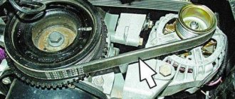
The next step is to remove the diode bridge; this requires the following steps:
- Use a wrench to unscrew the nut that secures contact number 30.
- Next to this pin there is a block with a plug. This element must be dismantled. But you should first release the fastener using a small flat-head screwdriver.
- The latch is disconnected from the inside. Then the block with wires is pushed inside. The plug should remain on the cover. The diode bridge is dismantled from it.
- The next step requires a vice. The rotor mechanism must be clamped into the equipment so that the rear bearing device is located on the top.
- Using a puller, the part is dismantled. To do this, you need to put the tool on top of the assembly and pull the bearing element off the pulley.
Unscrewing the generator impeller
Disconnecting pin 30, connector and dismantling the diode bridge
Removing the bearing device from the pulley
After disassembling the elements of the generating set, replacing the failed components:
- To change bearing parts, you need to check the markings of the elements. Similar spare parts are purchased at the auto store. Even if the bearings are visually intact, it is recommended to replace them. The parts are not interchangeable, so when purchasing, be sure to follow the markings.
- The same goes for the diode bridge. The markings are rewritten from the part, only after that the spare part is purchased. If there is visible damage to this device or metal oxidation has occurred, the unit must be replaced. It is fixed to the generator housing with four nuts. The diode bridge is located at the back, on the inside.
- A visual diagnosis of the front cover of the generating set is carried out. If there are cracks or other damage, the casing must be replaced. When performing visual diagnostics, it is important to pay attention to the fastening elements.
- The diameter of the seat for the bearing parts in the front cover is measured. If the socket for their installation is more than 4.2 cm in diameter, the cover must be replaced.
- Then a visual check is made of the rear of the unit. If there is damage on it in the form of cracks, it must be replaced. Wear or breakage of the seating area under the bearing element is not allowed. If such damage occurs, the cover must be replaced.
- Visual diagnostics of the internal surface of the stator device is carried out. Scratches and other defects resulting from touching the anchor are not allowed. If wear is detected, the bearing elements or the generator set cover are replaced.
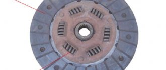
The winding of the dismantled rotor mechanism is checked, the task is carried out as follows:
- It is necessary to visually inspect the slip rings. These elements must be replaced if defects are found. We are talking about signs of wear, scuffs, scratches, etc. In principle, the rings do not need to be replaced if the damage is minor. But then they will have to be sanded, for this you will need fine-grained sandpaper.
- If damage to the elements cannot be removed with sandpaper, you can try turning them on a lathe. When using the equipment, it is necessary to remove a minimum layer of metal and then sand the surface.
- Using a tester, the resistance value of the winding of the rotor mechanism is checked. To do this, the device must be connected to slip rings. If the diagnostics show that the resistance tends to infinity, this indicates a break inside the winding. To correct the problem, you will need to replace the rotor mechanism.
- Using a test lamp, a diagnosis is made of the absence of a short circuit in the winding of the anchor device on the housing. To do this, you need to activate the light source by connecting it to the battery. One contact is connected to the body of the anchor device, and the other is connected to each ring in turn. The indicator light should not light up when the rotor is operational. If it is activated, this indicates a short circuit in the winding, then the armature will need to be replaced.
Vyacheslav Lyakhov spoke in detail about performing diagnostics, as well as repairing the unit in the VAZ 2109 car.
Generator assembly
If you managed to disassemble and repair the unit, then after completing the work you will need to put it back together:
- The rear bearing device is installed at the landing site, on the shaft. A wooden board and a hammer are used to complete the task. The bearing is carefully driven in so as not to damage the part. To do this, just hit it several times.
- If the diode bridge was dismantled, it must be reinstalled. The device is located in the back cover of the case.
- The protective casing is then installed on the anchor device so that the bearing element is completely seated. To simplify the action, you can use a hammer. Light blows on the cover clog the bearing; it must be placed on the pulley. The same part installed on the front cover is replaced and fixed using plates.
- Then the generator device is dismantled from the vice. Before installing the front cover on the assembly, the spacer ring is mounted on the pulley. This part should be located between the thrust recess and the front bearing device.
- The cover is installed from the front, the stud nuts are tightened using the crosswise method. This will ensure more uniform tightening of the fastening elements.
- The stud is installed in the recess on the shaft of the anchor device. Then the impeller is installed, the element is clamped with a nut.
- At this point, the assembly procedure for the generator device can be considered complete. All that remains is to install the voltage regulator with brushes at the landing site.
Evgeny Bragin described the assembly procedures for the “nine” unit, indicating all the nuances of this process.
Installation and connection
Installation of the generator unit is carried out in the reverse order; when performing this task, it is important not to forget to connect the wire to the control device:
- A fixation bracket is screwed to the installation. A wrench is used.
- The bracket is then screwed into place with the generator set. When performing this task, you do not need to tighten the nut all the way.
- Self-tapping screws are used to secure the unit's dust protection.
- The drive belt is being installed on the generator set pulley.
- The tensioning element strip is being installed.
- The drive belt is tensioned. When performing this task, it is important that the deflection of the product is about 1-1.5 centimeters. When tightening the belt, it is necessary to tighten the nut on the tensioner bar. Then this element is clamped on the bracket until it stops.
After the installation is completed, you need to connect the terminal blocks to the generator device. When performing the task, you need to make sure that the clamps are disconnected from the battery. There should be a total of three wires connected to the unit. Paired cables are secured with nuts to a stud located on the back cover. A male connector must be installed in a female connector.
Then the terminal clamps are installed on the battery, and the power unit is started. The generator unit supplies the voltage required for full operation of all machine devices.
To be sure that the unit is working properly, you need to use a voltmeter to diagnose the voltage that the unit produces.
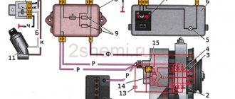
Generator set connection diagram
Generator bulkhead 37.3701 for 21093 — Lada 2109, 1.5 l., 1998 on DRIVE2
We will talk about disassembling and reassembling a standard generator for carburetor 21093, type 37.3701 - 55A. When warming up after an overnight stay, a howl became clearly audible from the generator. When removing the belt from the generator with the engine running, there was no howl.
Replacing the belt, tensioning and loosening did not lead to anything. Checking the generator on the car using a test lamp or a multimeter using the methods described in the repair manual also did not reveal anything. Everything seems fine.
Roughly speaking, the bearings remain suspect.
It was decided to remove it, disassemble it, and look at it.
The generator can be easily removed. Without a hole, on level ground. There is nothing to describe.
I brought the generator home. The most difficult thing was to remove the pulley. Well, I don’t understand what they were thinking when designing this miracle? Why couldn’t they make some turnkey flats on the rotor shaft (as an option)? I tried to unscrew it in different ways. In the end I did this .I completely unscrewed all the coupling bolts (these are the longest and connect the two halves of the generator).
He pulled out the boots and placed the bolt heads between the cooling fins on the pulley - i.e. the heads of the bolts did not allow the pulley to turn. And thus I was able to unscrew the pulley nut. You can use a sharp, not too strong blow to break off the pulley nut at the end of the wrench with which we unscrew it. Yes, the ribs were quite slightly wrinkled - but they were simply leveled out with pliers.
I pulled these tightening bolts up and used them as stops and clamps.
Next, let's define the concepts. The front cover is the part of the housing closer to the generator shaft. The rear cover is the part of the housing that is closer to the battery. The rotor shaft came out of the bearing of the front cover of the generator freely.
The rear bearing sat more tightly in the housing. To remove the rear bearing, I had to use a simple puller. This will be enough for a couple of times. But in general, the thing is not very serious.
When pressing out the bearing, the plates in the puller were bent - the retainers. In general, here is the puller itself.
Generator bearing puller.
And here are its plates after removing one bearing.
Curved plates.
Since everything was sorted out, I rang the Murzilka again - I didn’t find any obvious crime. And I didn’t have and probably never will have special equipment for checking. I began to study the bearings. First, the rear one.
Before removal.
The rear bearing (the one towards the battery), on the side of the regulator brushes, was dirty as a hundred devils.
Rear bearing (dirt).
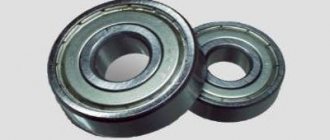
Its marking is 6201RS.
Marking.
I removed the protective rings from it. Twisted it and looked inside. There was a slight play. Well, the grease looked sad :).
Inside.
In general, it was decided to change it. Press in a new bearing (as simple as that) with a suitable head from a set of tools and a hammer. The head presses on the inner ring of the rear cover bearing. At first I wanted to take a European brand bearing. But they had a long delivery time. In the end I settled on Japanese Koyo. Fortunately Exist is nearby.
In general, finishing with the rear bearing, it turned out that the old bearing easily came out of the rear cover, but it was difficult to remove it from the shaft. The new Koyo bearing fit into the back cover with almost a gap. Although the sizes are the same.
Koyo. Small in the back cover, large in the front.
I had to tinker with the front cover. Firstly, it was difficult to unscrew the four bolts that tighten the plates between which the bearing is located. Again, a miracle of engineering and subsequent convenience.
Unfortunately, it got so bad that I didn’t take a photo. Photo from "Behind the Wheel".
Our plate mount.
Near the almost flat and round head of each of the four bolts, there are, as it were, triangular “kerchiefs” from the head to the bolt shaft. Two gussets per bolt.
These “kerchiefs” should prevent the bolt from turning (when tightening it or unscrewing the nut from it) in the plate covering the bearing. Again, it should, this does not mean that it is like that! I was exhausted trying to keep the bolt from turning.
Then, out of curiosity, I looked at how this unit is organized on imported generators? It’s simple. Humanly speaking. On a Valeo generator for Nissan, this bolt can be kept from turning with a sprocket bat.
Nissan bolt.
In the VAZ spare parts catalog there are plates, and these bolts, and tightening bolts for the generator. However, the chances of finding them on sale are equal to the chances of buying original fog lamp brackets. In general, I removed the plates. I hit the bearing once, and it came out of the silumin cover.
But the new bearing fit into the front cover with great difficulty. I was already afraid that it would burst. Here you go - the same sizes of bearings. But nothing. I installed it. Again, a hammer and a head. We apply force to the outer (outer) ring of the bearing.
Here is the actual stock front cover bearing (on the left, larger).
The stock front cover bearing is on the left.
And here are the markings of the stock bearings.
Marking
New Koyo bearing in front cover.
New bearing in the front cover.
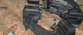
Horseshoe.
Horseshoe (rectifier block).
Horseshoe markings.
Horseshoe markings.
Inside view.
View towards the rear bearing (the bearing is not standing).
The client is ready (later the voltage regulator was changed to VTN 1702.3702-01).
Everything is collected.
After installing the assembled generator on the car, the howling disappeared. However, if you put your hand on the generator while the engine was running, a slight vibration was felt. It's true that everything went away with time. Maybe the bearings have “settled” into place. In the future I plan to install a 73A generator.
- “Decimal” ones do not suit me in terms of fasteners because I have a pure carb block.
Package.
Safety precautions when working
Nuances that must be taken into account when repairing a VAZ 2109 generator:
- All control and adjustment work related to diagnosing the unit with the engine running must be carried out in a ventilated area or outdoors. If it is a garage, it is recommended to open the doors or provide good ventilation.
- Before carrying out the task, you need to button up your sleeves if the work is performed in a shirt. All hanging ends of clothing should be removed to prevent them from getting caught on the operating pulley.
- To carry out repairs, a specialized tool is used.
- The generator must not be allowed to fall after it has been removed during transportation to the machine. This can lead to complete failure of the unit.
- Repairs should only be carried out using serviceable, clean and oil-free tools.
- If the nuts are rusty and difficult to unscrew, it is recommended to treat the elements with kerosene or WD-40 before turning them out. Dismantling is carried out with preliminary tapping with light blows of a hammer.
- The vehicle is inspected using a 36-volt light bulb. If the diagnosis is performed in a ditch, a 12 V light source will be required. It is important that the light bulb is equipped with a safety net.
Why is the battery not charging?
Before writing about the main reasons why the battery may not charge on VAZ 2109-2108 cars, I would like to warn all readers that the list I have given is not complete and is compiled only based on personal operating experience. So, during my short 10 years of driving experience, I had to operate a lot of cars and there were quite a lot of problems with charging the battery, and I will try to write about the main ones here.
It's no secret that the main device that is responsible for the normal operation of electrical appliances in a car is the generator. It is precisely because of the failure of some of its parts that charging may disappear completely or become weak. The main malfunctions of the generator, which entail a decrease in the charge current to the battery:
- Wear of generator brushes. This is a very common and most common reason. If they are worn down to the minimum permissible height, then the charge may disappear gradually, and then disappear altogether. To solve this problem, you just need to replace the brushes with new ones and that’s it.
- Failure of the diode bridge. The most reliable diode bridges are usually installed on VAZ 2109-2108 cars from the factory. And they are the ones who travel the most kilometers! This has already been tested not only by me, and any experienced auto electrician will confirm this. If one of the diodes or the entire rectifier unit burns out, then it also needs to be replaced. The procedure is not very fast and pleasant, but it will not cause much difficulty. Just below I’ll put a link to a page that describes the entire generator repair process.
- A more complex generator breakdown, such as a break in the rotor or stator winding. Of course, this is rare, but it still happens sometimes. The cost of these spare parts is quite low, so it is better to buy new ones and install the burned ones together than to buy a new generator.
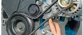
- Poor charging may be due to slipping of the alternator belt. This becomes especially noticeable in damp or rainy weather, or when water gets on the belt. It begins to whistle, causing it to slip on the pulley, thereby preventing the generator from gaining sufficient speed to optimally charge the battery.
If you have problems with your car that are described above, then you can read all the maintenance procedures here: Repairing a generator on a VAZ 2109-2108 with your own hands. Everything is described there in quite detail and even for beginners the information will be very useful, and understanding it will not be difficult.
Repair costs
The approximate cost of spare parts is shown in the table.
| Name | Price, rub |
| Price of a set of bearing elements | Around 150 rubles. |
| Generator diode bridge | 200 rub. |
| Charging relay | About 150-200 rub. |
| Removal tool for bearing elements | Around 100-200 rubles. |
| Prices are relevant for three regions: Moscow, Chelyabinsk, Krasnodar. | |
Loading …
Replacing brushes on the carburetor and injector with removal of the generator
- First loosen the generator.
- Remove the alternator belt. Please note that an inoperative alternator belt may also be a symptom of alternator problems. To check the belt, you need to bend it and inspect the surface for cracks. If there is deformation, replace the belt.
- Start the engine.
- De-energize the battery by removing the ground wire. This operation must be carried out to prevent a short circuit.
- Remove the wire going to the generator.
- Remove the engine crankcase protection.
- Unscrew the bolt that secures the generator from below.
- Lock the rotor with a minus screwdriver to immobilize it.
- Unscrew the pulley.
- Remove the generator casing.
- Remove the plastic protection to gain access to the generator brushes.
- Using a screwdriver, hook the power plug that comes from the brush holder.
- Pull the brush holder up. You must continue to apply force until it is removed. Perform the operation more carefully so as not to damage the soldering.
- Remove the plug and brushes of the generator.
- Unscrew the bolts securing the brushes, as well as the brush holder.
- Remove the voltage regulator. Remove the brushes and the brush holder. Don't be afraid of damaging them, because they will have to be replaced anyway.
- Remove the two pairs of bolts securing the two parts of the generator.
- Remove the back cover. To do this, you need to insert the generator and the cover into the slot. Pull up. This way you will remove the cover.
- Screw the nut onto the generator rotor.
- Carefully remove the generator.
- Visually inspect the generator parts for wear. If it is too big, replace them.
- Loosen the brush holder bolt.
- Replace the generator brushes with good ones.
- Reassemble in the opposite order and install the generator in its place.