Possible reasons for failure of the ignition module
Before repairing the main part in the car’s ignition system, you need to understand the nature of the problem. To do this, the consumer must be aware of the signs of a malfunction, as well as the causes of the breakdown.
The main reasons for device failure
Causes of problems:
- The ignition system uses spark plugs that do not match the vehicle parameters. They may not have the gap specified by the manufacturer. Also, the spark plugs themselves may not be working or dirty; this can be determined by visual diagnostics. If there are traces of carbon deposits on the devices, they must be removed.
- Malfunctions in the operation of the MH can arise as a result of frequent spark checks. At the time of diagnosis, a high load is placed on the device. If it appears frequently, it will lead to equipment failure or incorrect operation.
- The ignition module in the VAZ 2114 operates with the high-voltage cables disconnected. This also leads to device failure. The products themselves may be damaged, which affects the functioning of the engine as a whole.
- The device operates under severe vibration conditions. Their impact may be due to poor quality fixation of the module in the seat. As a result of vibrations, the factory soldering inside the equipment structure is damaged. This leads to its incorrect operation.
- The contact inside the plug with the low-voltage cables is broken.
- Initial use of a defective device or module with poor build quality. This factory defect can only be eliminated by replacing the mechanism; repairing the equipment is pointless.
- Moisture getting inside the case. This problem is unlikely, but exposure of the device to liquid may cause it to short out and break.
Signs of coil malfunction
The main symptoms of a malfunction in the VAZ 2114 ignition module:
- Difficulties arise when trying to start the engine. Starting the car engine may be difficult due to the fact that there is no spark on a spark plug or several.
- When idling or parking with the internal combustion engine running, the speed of the power unit floats. Their change is not associated with pressing the gas pedal and other third-party factors. This happens randomly.
- There are dips in the power of the car's engine. This is especially felt when driving uphill or sharp acceleration. Problems can also occur when driving on a flat road.
- Several cylinders stopped working. Usually these devices operate in pairs, so elements 1-4 or 2-3 could fail. Non-working cylinders may be indicated by “triple movement” of the engine.
- A “Check Engine” warning light appeared on the dashboard.
If the ignition module malfunctions, problems will appear not only in engine operation, but also when starting it.
The “Simple Opinion” channel, using the Lada Priora car as an example, spoke in detail about the symptoms that appear in the operation of the ignition modules.
Ignition module diagram 2115
The circuit diagram and connection diagram of this electronic device is presented below.
The ignition module installed on the Lada Samara is extremely resistant to both low and high temperatures. Operating temperature range: -400/+1300C.
The only negative point in the operation of this electronic device is its complete inability to repair. However, even a novice car enthusiast can replace it on his own.
Experts consider the most common malfunctions of the Samara ignition module to be:
- Unstable operation of the power plant when accelerating the vehicle.
- Decrease in engine power.
- “Intermittent” idle speed.
- Malfunction of paired (1/4 – 2/3) engine cylinders.
Attention! The detection of the above malfunctions is not final evidence of failure of the ignition module, since similar symptoms are possible due to malfunctions of the spark plugs and unreliable connection of high-voltage wires.
How to check the malfunction of the VAZ 2114 ignition module on your own?
The easiest way to check the device without removing it is to diagnose it at the moment the power unit is tripped. When the motor begins to operate unstably, it is necessary to disconnect the connector elements from each component of the module one by one. If the connector is disconnected from a functioning device, the operation of the engine will change. Dips will appear, and the unstable operation of the unit will increase. When the non-working element of the MH is disconnected, the motor will operate in the same way.
There is another simple diagnostic method, its principle is as follows:
- You will need an assistant to check. The spark plug is removed from the seat. The high-voltage cable is disconnected from the device.
- Then the disconnected wire is connected to a spark plug, which is applied to the body of the power unit.
- The machine motor is starting, you need to make sure that a spark hits the spark plug. If it passes, a blue light will appear between the device and the surface of the power unit, its formation is accompanied by a crackling sound. If there is no spark, then the spark plugs, high-voltage cable and module must be diagnosed.
Replacing the ignition module on a VAZ 2113, VAZ 2114, VAZ 2115
When do you need to change the ignition module? It can fail at any time, and the signs it will show in the event of a malfunction are as follows:
- The car may move jerkily.
- It is also possible that the engine speed will fluctuate.
- To all this, unstable operation of the engine at idle may also be added, that is, it will simply stall.
For what malfunctions is it possible to repair the device?
Due to the fact that the ignition module by design includes a connection of two coils, it is difficult to repair. If there is a break or breakdown, as well as melting of the turns, the problem can be solved by replacing the device. This applies to any damage that appears inside the coils. The only option to correct the situation without replacing the device is to repair the damage to the solder joint.
Ignition module repair process
The repair procedure is carried out after preparing all tools and materials:
- a set of socket wrenches, you will need a tool for 10, 13 and 17;
- hexagon 5;
- flat head screwdriver;
- soldering iron with aluminum and flux;
- nail polish;
- multi-core conductors.
Restoring the ignition module operation is done as follows:
- The key is installed in the switch. The engine starts. Then you need to move the contact elements on the module to make sure they are not working.
- The power unit stops. The module is being removed.
- The device body is cleaned from dust. To disassemble, you need to open the case; this is done by prying it off with a screwdriver. Inside the device there is a board on which there is a silicone film; you need to get rid of it.
- Aluminum is removed from high-voltage contact elements. Old wires are removed.
- The next step will be soldering new conductors to the circuit. To do this, the surface of the collector device is cleaned from traces of plaque. Then the board must be installed on an electric stove and heated to approximately 200 degrees. As the temperature increases, a slight burning smell may be heard. This is not a problem for the circuit; heating it will simplify the soldering procedure.
- Then soldering is done. Using a soldering iron, flux and aluminum, the ends of the conductors must be connected to the ignition module. All contact elements of the conductors that are connected to the circuit must be treated with nail polish.
- Then the device is assembled in the reverse order and installed in the seat. After installation, the power unit starts up. If the repair solves the problem, then using a sealant, the device is fixed in place.
- If a transistor or switching device fails, then these components cannot be repaired, but they can be replaced. To do this, the parts are removed from the board and replaced with new ones.
Ignition module VAZ 2115 - check, malfunctions and replacement
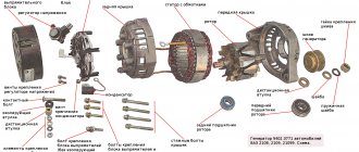
To begin with, I would like to note that the ignition module on the VAZ 2115 is a fundamentally new device that is more reliable than what was installed on earlier models of VAZ cars. The essence of the operation of this device is that it produces a high voltage electric current, which is subsequently transmitted to the spark plugs of the vehicle’s ignition system.
Operating principle of the ignition module
As mentioned earlier, the main task of the ignition module is that it generates a high level of voltage, which is subsequently transmitted to the spark plugs. The generated current undergoes a compression procedure, as a result of which a working spark is supplied to one of the spark plugs of the ignition system, and an “idle” spark is supplied to the second. To be more correct in statements, the working spark is supplied to the first and fourth spark plugs of the vehicle’s ignition system, and the “idle” spark is supplied to the second and third. Thanks to this high-voltage electric current supply system, the spark appears at the right stroke and on the right cylinder, which ensures stable operation of the system.
Video. Checking the ignition module of the VAZ 2115
Power to the VAZ 2115 ignition module is supplied directly from the vehicle’s on-board electrical network. The voltage supplied to the ignition module is twelve volts. At the same time, you should know that the negative wire of the ignition module is attached directly to the vehicle body. Design of the VAZ 2115 ignition module
The vehicle ignition module consists of a housing made of plastic, a pair of electronic control units, a pair of high-voltage current transformers, and four outputs for BB-type wires. Dimensions of the VAZ 2115 ignition module: one hundred ten by one hundred seventeen by seventy. The weight of the ignition module is one kilogram, three hundred and twenty grams.
Operating principle of the ignition module
The supply of electric current is carried out using wires of the BB type; the supply of electric current is controlled using a special controller, which makes decisions based on information that comes to it from various sensors of the vehicle. Also, the controller’s tasks include setting the sequence in which the ignition coil operates.
The ignition module can carry out its uninterrupted operation at temperatures from minus forty degrees to plus one hundred and thirty degrees Celsius.
What are the signs that indicate a faulty ignition module?
There are several typical signs that directly indicate problems with the ignition module:
1. The engine idle is floating. 2. Engine thrust periodically disappears for no reason. 3. The car picks up engine speed very slowly when accelerating. 4. The cylinders stop working in pairs.
Note that the same signs indicate a malfunction of the BB wires and spark plugs of the vehicle’s ignition system, so in the beginning, you should check them, and if everything is fine with them, then replace the ignition module. Tools you will need:
To replace the ignition module on a VAZ 2115 car, you will need very few tools:
1. Open-end wrenches for seventeen and thirteen. 2. Ten socket wrench. 3. Hexagon. Replacing the ignition module on a VAZ 2115 with your own hands
To independently replace the ignition module on a VAZ 2115, you should strictly adhere to a certain sequence of actions, which you can find below:
1. First, you must find the ignition module itself in the engine compartment. This can be done by following the high-voltage wires that come from the spark plugs of the ignition system.
2. Next, you must disconnect the negative cable from the battery.
3. Now, you need to remove the block to which the wires are connected from the ignition module.
4. Next, you should disconnect the high-voltage wires.
5. Now, you can unscrew the mounting bolts that secure the ignition module to the engine and remove it.
6. Then all you have to do is mount the new ignition module and assemble the entire structure in reverse order.
Replacing the ignition module of a VAZ 2114
If repairing the MZ VAZ 2114 is impractical or impossible, then the problem with the operation of the device can be solved by replacing it.
The equipment needs to be changed only when the battery is disconnected. Otherwise, there is a risk of short circuits and failure of other electrical appliances.
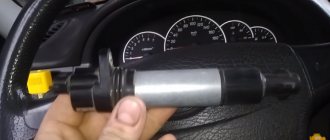
How to remove the ignition module of a VAZ 2114?
The dismantling procedure is performed as follows:
- First, the on-board network is de-energized; to do this, loosen the negative clamp on the battery with a wrench.
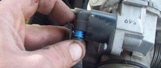
- Then a search for MH is performed in the engine compartment. You can find the device by four high-voltage wires that go from the spark plugs directly to the equipment. These cables are disconnected from the MH.
- Then the connector with conductors is disconnected from the device. It is necessary to disconnect the fixing fastener located on the ignition module housing.
- The MZ itself is secured to the bracket thanks to three nuts. You need to unscrew them using a key.
- After dismantling the fasteners, the device located on three studs is removed.
Connecting a new device
The equipment installation procedure is performed in reverse order; during installation, the following nuances must be taken into account:
- After installing the ignition module, you need to look at its surface. It is marked with numbers - 1, 2, 3 and 4. These symbols indicate the numbers of the cylinders to which the MZ should be connected.
- To properly connect the device, you need to look at the ends of the high-voltage cables. They are also marked with the same numbers. This is done in order to simplify the procedure for connecting the MH to the cables.
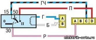
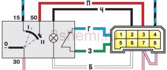
Connection diagram
The device must be connected in accordance with the diagram given in this section.
Connection diagram for MZ on VAZ 2114
How to check the device after connection?
Diagnostics of the operation of the new VAZ 2114 ignition module can only be performed using a special device - a high-voltage arrester.
You can find it in almost any auto store. Using the equipment, you can diagnose the module, as well as high-voltage cables, for the presence of a spark. To check, you need to connect the device to the device and use its operating instructions.
Design of the VAZ 2115 ignition module
This module consists of two high-voltage transformers and two control units (electronic), enclosed in a durable plastic case with four outputs of high-voltage wires. Electronic control units are also commonly called ignition coils, and one of them - “working” - is connected to the spark plugs of the first and fourth cylinders of the power unit, the other - “idle” - with the spark plugs of the second and third.
This type of connection, made using high-voltage wires, ensures synchronous “slippage” of the spark pulse in the cylinders of the power plant.
Thus, we can formulate the functional purpose of the ignition module - generating high-voltage spark pulses on the spark plugs of the vehicle's power unit.
The VAZ 2115 ignition module is controlled by a controller whose operating functions include processing data received from vehicle system sensors: coolant temperature, rotation speed and position of the crankshaft, air flow, presence of detonation, etc.
What should I do if the problem remains after replacing the module?
If, after performing the repair, problems in the operation of the MH remain, then there is a possibility that the cause of the problem was not in the module. It is necessary to diagnose the remaining elements of the ignition system.
Spark plugs and ignition system
Features of checking spark plugs and other components:
- Before dismantling the devices, it is necessary to disconnect the ends of the high-voltage cables. Their condition is checked for damage. Defects in the tips often lead to malfunctions in the spark plugs. If there is damage, the wires are replaced. It is also necessary to assess the condition of the “high-voltage workers” themselves. They are not allowed to have any defects or damage to the insulation.
- After disconnecting the tips, the spark plugs are dismantled and a special spark plug wrench is used to unscrew them.
- After dismantling, the condition of the devices is assessed. The color of the parts must be brown; carbon deposits and soot on the electrodes are not allowed. If there are uncharacteristic marks, the devices are cleaned using a metal brush or fine-grained sandpaper. For a better effect, the electrodes of the candles can be heated on the stove.
- The condition of the gap between the part and the electrode element is checked. If it is too large, this indicates that the device is not working correctly. The spark plugs will need to be replaced.
Ignition circuit for VAZ-2113, 2114, 2115
The ignition circuit in the VAZ-2114 is almost completely identical to models 2113 and 2115 and includes a coil, wires, switch, module, etc. The main task of the parts is to generate voltage, which enters the spark plugs and causes them to create a spark.
Ignition system diagram
A high-voltage coil ensures ignition of the fuel-air mixture, regardless of whether they are injection or carburetor engines with a sensor. With the advent of contactless power systems, distributors (distributors) are a thing of the past. They were replaced by new schemes from the VAZ-2114, the operating principle of which is based on the logic of standard structures. In older systems, voltage was generated by disconnecting the contacts. In new ones, the signals are supplied by a control unit, which collects signals coming from sensors on the motor, forms them into a control pulse and sends them to the ignition circuit. High voltage is generated by two coils and a two-channel electronic switch.
The system includes:
- Hall Sensor.
Hall sensor location
- Module.
Ignition module
- On relay, as well as switch.
- Electronic switch.
Electronic switch location
- High voltage wires.
High voltage wires
Contactless connection is ensured by a low-voltage power supply connector. High-voltage wires are connected directly to the spark plugs.
If there are problems in the unit, you must first check the spark plugs.
To do this you need:
- Disconnect the armor wire ends.
Disconnecting the tips
- Unscrew the spark plugs with a key number 17. Based on their condition, the specialist will determine the location of the problem.
Unscrew the spark plugs with a 17 key
The carburetor is checked last. In fact, this part can only be replaced.
Examination
Checking the VAZ 2114 ignition module is carried out as follows.
First of all, you need to check the block of wires that go to it. To do this, disconnect the block of wires, take a tester and connect one of its probes to the block, and connect the other to engine ground. Now look at the tester readings: the voltage should be around 12V. If there is no voltage, then you need to check the fuse. Then take a 12V test light and connect it to pins A and B. Turn on the starter and watch: the lamp should blink, if it doesn’t blink, therefore, there is an open circuit on pin A. Perform a similar operation with pin B. So, how to check the ignition module VAZ 2114, 2115 (8 valve injector)? Today there are several verification methods. 1) The first method is to replace the unit with a known working one. Everything is simple here: take it from the donor car and replace it. But there are certain disadvantages here: - there may not be a donor car, buying a new unit does not suit our task - it will not fit any car. Not everything is so simple here: old Samaras with a 1.5 liter engine are equipped with an ignition module. New cars are often equipped with ignition coils. In them, the switch is located in the ECU - therefore, the module is eliminated as unnecessary, leaving only the coil. — you need to make sure that the high-voltage wires are in good condition, otherwise there is a possibility that the unit will burn out. 2) The second method is the method of moving the unit. If at the moment of your impact the engine operation changes, then the problem is poor contact. This malfunction is common, so you can try to repair the unit yourself. If it cannot be repaired, then it must be replaced with a new one. 3) To check you need a tester. Using a tester, measure the resistance at the paired terminals between cylinders 2 and 3, as well as between cylinders 1 and 4. The resistance should vary around 5.4 kOhm and be the same.
The 2111 (1.5i) engine may have an ignition module or an ignition coil installed. The 11183 (1.6i) engine is equipped with ignition coils.
To perform the work of replacing the ignition coil, you will need a multimeter.
Checking the ignition module
Checking the ignition module for functionality is carried out in the following ways:
Replacing the ignition module with a known good one
1. The easiest way is to connect a known working module. In this case, the devices must be completely identical, the high-voltage wires are in good condition, and the reliability of the contacts has been checked.
Checking the contacts on the ignition module
2. Moving the module, which allows you to identify unreliable contacts. To do this, move the wire block and the module itself. If during exposure the engine reacts by changing its operation, then the cause of the problem lies in poor contact.
Measuring resistance at the terminals of the ignition module
3. Resistance measurement. To do this, you will need a tester switched to ohmmeter mode. Measurements are carried out on the paired terminals of the module between cylinders 1 and 4, as well as cylinders 2 and 3. The resistance value should be the same and approach 5.4 kOhm.
Checking the ignition module using a tester
4. Check the voltage with a tester. One probe of the device is applied to contact A of the block, the second to ground. After turning on the ignition, take readings from the device. If the wire is in good condition, it will show a voltage of 12 V; if it is missing, check the fuse protecting the ignition module. Then check the continuity of the circuit with a 12 V test lamp. Apply one end of the wire to contact A and rotate the starter. If the lamp does not blink, the circuit is broken. The procedure is repeated in a similar way with other contacts.
Diagnostics of the ignition module with professional equipment
5. Diagnostics at a service station by connecting a computer with special software to the computer. Malfunctions are detected in the form of errors indicated by an alphanumeric code, after which a more in-depth diagnosis of the malfunction is carried out to make a decision - repair the ignition module or replace it. A similar check is carried out at a specialized service station using an oscilloscope.
Withdrawal procedure
Release the lock and disconnect the wires from the ignition coil terminals.- Turn on the ignition and use a voltmeter to measure the voltage between terminal 15 and ground in the case of an ignition coil or between terminals C and D in the case of an ignition module on the wiring harness block. The voltage must be at least 12 volts. If there is no voltage or it is less than needed, then you need to check the charge of the battery, computer or power circuit. To check the ignition coil, you can replace it with a known good one.
- After taking measurements, turn off the ignition.
- Disconnect the high-voltage wires from the spark plugs.
- Using a 13mm wrench, unscrew the 2 bolts of the upper mounting of the coil bracket.
- Using a 17mm wrench, loosen the lower mounting bolt of the bracket and remove it together with the coil.
- Disconnect the high-voltage wires from the ignition coil
- Using a multimeter in ohmmeter mode, we measure the resistance between the central terminal 15 and the housing. The multimeter should show that there is no short circuit of the primary winding of the coil to ground. We sequentially measure the electrical resistance between the central terminal 15 and the outer terminals - 1a and 1b. The resistance of each of the primary windings of the coil should be about 0.5 ohms. When taking measurements, you need to take into account the device's own resistance.
- Using an ohmmeter, we measure the resistance between the high-voltage terminals of the coil 1 and 4, and then 2 and 3. The resistance of the windings should be about 5.4 kOhm.
- Using a 5mm hex wrench, unscrew the 4 screws securing the coil to the bracket and remove the coil.