Instructions for replacing instrument panel 2101 with 2106
Replacing the instrument panel 2101 with 2106 technologically consists of the following stages: mechanical installation and electrical connection. I’ll make a reservation right away that some types of work listed below may differ in real life from what is stated, due to the low quality of the instrument panels currently available for sale. I’ll immediately note that a 2106 radio panel (console) was installed on the 2106 dashboard, so some points may be written in relation to such an installation. Also in the photo there is other non-standard wiring (under the central locking, etc.) - don’t be alarmed, to ours It has nothing to do with the topic.
So the available source materials:
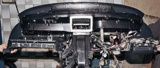
Instrument panel assembled with instruments Fig. 1. (positions 1, 5-9,15-19 are required. Positions 2,3,10 can be taken from 2101, bracket 14 is required when installing console 2106)
Figure 1 – Instrument panel
In Figure 2, in the “glove compartment” section, element 2101-5303015 is shown as the side of the glove compartment, which in fact does not correspond to reality (probably a typo in the book), because panel 2106 in cross-section has a different configuration - you can try to find the part on the market or cut out of plastic according to location.
Figure 2 – catalog numbers
The next necessary spare part is the wiring harness for devices 2106 - Figure 3 - 2106-3724030.
Figure 3 – Wiring harness and instruments
When I asked for a harness on the market, they offered me an “adapter from 2101 to 2106”, upon detailed study it turned out that the difference from those shown in the diagram is that the “adapter” does not have an output to the handbrake lamp relay (2101-3803150), because . on the 2101 relay it hangs on the wires entering the cabin. That is, you can take the standard 2106 harness without any hesitation and move the relay.
Although on the new 2106 circuits there is no relay on the handbrake at all, in this case the “adapter” can essentially just be a harness from the electrical equipment 2106 of the new model.
Limit switch for suction – Fig. 3 – 2101-3803130
Choke, or its handle with a protrusion for the switch - Fig. 4 - 2103-1108100
To connect to the 2106 wiring harness, you need an empty 8-pin connector (female)
In order for the oil pressure indicator to work, you need to buy an MM393A sensor (2103-3810300 - Fig. 4) and a tee (2103-3810610, 10282460), a rubber boot for the contact of the MM393A sensor (2101-3724114)
Speedometer cable from VAZ2103, -06 – If you leave the standard speedometer cable, then the longer cable 2101, when installing the instruments, bends with too small a radius, which is why the needle may tremble! The price of cable 2103 today is 20 UAH, is it worth saving on this?
Levers for the stove and air damper - Fig. 5 2103-8109020-10. The levers, unlike the 2101, are designed to be attached not to the dashboard, but to a metal cross member for the lower mounting of the dashboard.
Mechanical speedometer for VAZ 2106
Mechanical devices are considered as simple as possible, since the essence of their work lies in the connection between the elements of the car. Thus, the mechanical device on the VAZ 2106 works on the principle of connecting the speedometer needle with the output shaft of the gearbox. The gearbox itself receives drive force from the rotation of the wheelset. Thus, the needle receives energy from the car wheel and reflects the corresponding value on the instrument scale.
In the cavity of the “six” manual transmission there is an output roller on which the gear is mounted. During movement, the gear rotates on this roller and touches the cable of the device. The cable is a very strong cable wrapped in protection. One end of the cable is mounted in the hole of this gear, and the other is connected to a speed meter.
Malfunctions
The good thing about a mechanical speedometer is that it is easy to identify problems with its operation and diagnose the malfunction. Conventionally, all possible malfunctions can be divided into two types:
- the speedometer does not show the actual speed of the car;
- The drive part of the device makes a lot of noise.
The reasons for these malfunctions include:
- A general malfunction of the speedometer itself - in this case, replacing the device is impossible.
- Loosening the flex shaft end nuts. While driving on uneven roads, the nuts can get loose - just tighten them all the way for the speedometer to start showing correct data.
- Breakage of the flexible roller in the gearbox. This part will need to be replaced.
- Damage to the cable. It is impossible to restore its integrity; it will have to be changed.
If you look at the statistics of breakdowns of the VAZ 2106 mechanical speedometer, you can conclude: a large number of faults are associated with the cable and can only be eliminated by replacing it.
Repair work
In order to restore the functionality of the mechanical speedometer, you will need:
- screwdriver with a flat thin blade;
- pliers;
- spanners;
- steel wire with a diameter of up to 0.5 mm and a length of up to 2 meters.
- new drive cable.
Since the drive part of the VAZ 2106 gearbox is mounted in the lower part of the car, you will have to use a pit or overpass for repairs.
The work order is as follows:
- Securely secure the car in such a position that it is convenient to crawl under it.
- Be sure to disconnect the wire from the negative terminal of the battery.
- Remove the instrument panel in the cabin by picking up the edge of the plastic with a screwdriver and pressing the latches.
- Unscrew the nut that secures the cable to the speedometer device.
- Tie a new wire to the nut.
- Unscrew the nut that holds the cable in the gearbox housing.
- Unplug the cable from the box.
- Pull the cable towards you, pull it out of the car so that the guide wire tied to the nut replaces the cable.
- Before installing a new cable, it is necessary to lubricate it with CV joint or Litol.
- Pull the new cable along the wire, then remove the wire.
- Perform all further actions to fix the cable in reverse order.
Thus, replacing the cable can take up to half an hour. In all other cases, it is advisable to immediately replace the speedometer itself - only a mechanical device can be installed for correct operation.
So, everything seems to have been pulled together, now let’s get to work:
We remove the standard tidy along with the steering wheel. Removing the instrument panel 2101 is described in detail in the manual for 2101. The steering wheel can not be removed, but then the inconvenience during operation greatly increases.
We try on the dashboard to the seats on the body. The differences in the 2101 and –06 devices immediately become visible:
We begin to eliminate the listed interference:
Installation of both stove levers and places for mismatched fastening (Fig. 6)
The heater valve cable is short. Looking carefully at the end of the cable that fits onto the heater valve lever, we see that it is twisted into a ring 3 times - this is the necessary reserve. Unwind the ring - leaving 1 turn (Figure 
The cables are sorted out. Now let's figure out where to place the offset fasteners!
We make a U-shaped bracket (Fig. 9)
Figure 9 – bracket for fastening
And we weld it to the intended place for fastening the dashboard -06. The result is a picture - Fig. 10
Figure 10 – Displacement of the fastening point
Now let's take care of the suction - we need to make brackets for it and place it approximately in the place of the old suction. The bracket is made according to TheForester's drawing (special thanks!)
Figure 11 – Homemade suction bracket
Figure 12 – Hand-made bracket for suction
We weld this example of crazy hands to the crossbar:
Figure 13 – Welded to the cross member
After welding, do not forget to prime to avoid rusting.
We insert a cable with suction into the manufactured bracket and screw in the end switch.
There is another important point - because. the speedometer in 2106 is shifted to the right than in 2101, then it is necessary to rewind the sidometer cable differently (see Fig. 14), however, due to the fact that the cable 2101 is longer, in the new place its length turns out to be excessive even after installing the panel due to excess radii If the cable bends, the speedometer needle may shake, so I recommend using a cable from 2103, 2106 that has a shorter length.
Figure 14 – location of the speedometer cable
This is where the mechanical part of the installation actually ends and the electrical part begins:
We screw the oil pressure indicator sensor with a tee (Fig. 4) and tighten the wire from the sensor into the passenger compartment, do not forget to put on the boot (2101-3724114 Fig. 4). We tighten the wire from terminal K - the ignition coil into the passenger compartment. We make a connection with the instrument panel harness 2106. The connection diagram when connecting new devices can differ greatly from model to model due to differences in the colors of the on-board network wires, and even the instrument panel harness 2106, so the correct one will be look at your diagram in place and make the appropriate connections.
In short, the decision comes down to a banal reconnection of wires. In 2101 there are 2 connectors of 6 contacts on the left and right, in 2106 - the left connector has 8 contacts, and the right one also has 6, like 2101.
Reconnecting the left connector:
From the existing left connector 2101, bending the contact locking plate, pull out the contact and insert it into the corresponding socket of the new 8-pin connector. We determine compliance using the paper diagram of our 2101 and 2106 harnesses. It often happens that the colors of the wires on the tank (on the CL contact and the rheostat) are mixed up - one option is indicated in the diagram, but in fact it’s the other way around. Having rearranged all 6 contacts of the left connector 2101 into a new 8-pin one, we deliver 2 more wires with contacts that we pre-tightened in steps 1 and 2.
Discontinued - old 6-pin connector 2101.
Reconnecting the right connector:
In principle, the number and list of wires here are the same, and it would seem that the VAZ designers should have left the sequence of wires similar to our 2101 (for the purpose of unification) - but NO, dear designers decided, at least a little, but to add a little more hassle to Kulibin like you and me, so here It also requires studying both schemes, searching for matches and rearranging contacts. To make it more clear, we rearrange it from the old 6-pin connector to the empty 6-pin connector we removed earlier in the previous paragraph of the text.
Connecting the buttons, I think, will not cause any problems.
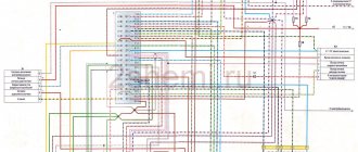
Since talking on paper is very good, but I also want something as an example, Figure 15 shows a diagram of the connection to the wiring of a VAZ 2101 (precisely 2101). The diagram should be used as a guide, not forgetting about possible differences in reality. I think it will help you figure it out faster.
Next, for complete similarity with the 2106, you need to install the 2106 tape recorder console, but this is not for everyone - and in fact the topic of a separate article, because there it will be necessary to install an emergency light, a fuel pressure control lamp, and a rheostat, which IMHO is not needed at all - it is better to leave the switch in the dashboard as in 2101.
Instructions for replacing instrument panel 2101 with 2106
Replacing the instrument panel 2101 with 2106 technologically consists of the following stages: mechanical installation and electrical connection. I’ll make a reservation right away that some types of work listed below may differ in real life from what is stated, due to the low quality of the instrument panels currently available for sale. I’ll immediately note that a 2106 radio panel (console) was installed on the 2106 dashboard, so some points may be written in relation to such an installation. Also in the photo there is other non-standard wiring (under the central locking, etc.) - don’t be alarmed, to ours It has nothing to do with the topic.
So the available source materials:
Instrument panel assembled with instruments Fig. 1. (positions 1, 5-9,15-19 are required. Positions 2,3,10 can be taken from 2101, bracket 14 is required when installing console 2106)
Figure 1 – Instrument panel
In Figure 2, in the “glove compartment” section, element 2101-5303015 is shown as the side of the glove compartment, which in fact does not correspond to reality (probably a typo in the book), because panel 2106 in cross-section has a different configuration - you can try to find the part on the market or cut out of plastic according to location.
Figure 2 – catalog numbers
The next necessary spare part is the wiring harness for devices 2106 - Figure 3 - 2106-3724030.
Figure 3 – Wiring harness and instruments
When I asked for a harness on the market, they offered me an “adapter from 2101 to 2106”, upon detailed study it turned out that the difference from those shown in the diagram is that the “adapter” does not have an output to the handbrake lamp relay (2101-3803150), because . on the 2101 relay it hangs on the wires entering the cabin. That is, you can take the standard 2106 harness without any hesitation and move the relay.
Although on the new 2106 circuits there is no relay on the handbrake at all, in this case the “adapter” can essentially just be a harness from the electrical equipment 2106 of the new model.
Limit switch for suction – Fig. 3 – 2101-3803130
Choke, or its handle with a protrusion for the switch - Fig. 4 - 2103-1108100
To connect to the 2106 wiring harness, you need an empty 8-pin connector (female)
In order for the oil pressure indicator to work, you need to buy an MM393A sensor (2103-3810300 - Fig. 4) and a tee (2103-3810610, 10282460), a rubber boot for the contact of the MM393A sensor (2101-3724114)
Speedometer cable from VAZ2103, -06 – If you leave the standard speedometer cable, then the longer cable 2101, when installing the instruments, bends with too small a radius, which is why the needle may tremble! The price of cable 2103 today is 20 UAH, is it worth saving on this?
Levers for the stove and air damper - Fig. 5 2103-8109020-10. The levers, unlike the 2101, are designed to be attached not to the dashboard, but to a metal cross member for the lower mounting of the dashboard.
So, everything seems to have been pulled together, now let’s get to work:
We remove the standard tidy along with the steering wheel. Removing the instrument panel 2101 is described in detail in the manual for 2101. The steering wheel can not be removed, but then the inconvenience during operation greatly increases.
We try on the dashboard to the seats on the body. The differences in the 2101 and –06 devices immediately become visible:
We begin to eliminate the listed interference:
Installation of both stove levers and places for mismatched fastening (Fig. 6)
The heater valve cable is short. Looking carefully at the end of the cable that fits onto the heater valve lever, we see that it is twisted into a ring 3 times - this is the necessary reserve. Unwind the ring - leaving 1 turn (Figure
The cables are sorted out. Now let's figure out where to place the offset fasteners!
We make a U-shaped bracket (Fig. 9)
Figure 9 – bracket for fastening
And we weld it to the intended place for fastening the dashboard -06. The result is a picture - Fig. 10
Figure 10 – Displacement of the fastening point
Now let's take care of the suction - we need to make brackets for it and place it approximately in the place of the old suction. The bracket is made according to TheForester's drawing (special thanks!)
Figure 11 – Homemade suction bracket
Figure 12 – Hand-made bracket for suction
We weld this example of crazy hands to the crossbar:
Figure 13 – Welded to the cross member
After welding, do not forget to prime to avoid rusting.
We insert a cable with suction into the manufactured bracket and screw in the end switch.
There is another important point - because. the speedometer in 2106 is shifted to the right than in 2101, then it is necessary to rewind the sidometer cable differently (see Fig. 14), however, due to the fact that the cable 2101 is longer, in the new place its length turns out to be excessive even after installing the panel due to excess radii If the cable bends, the speedometer needle may shake, so I recommend using a cable from 2103, 2106 that has a shorter length.
Figure 14 – location of the speedometer cable
This is where the mechanical part of the installation actually ends and the electrical part begins:
We screw the oil pressure indicator sensor with a tee (Fig. 4) and tighten the wire from the sensor into the passenger compartment, do not forget to put on the boot (2101-3724114 Fig. 4). We tighten the wire from terminal K - the ignition coil into the passenger compartment. We make a connection with the instrument panel harness 2106. The connection diagram when connecting new devices can differ greatly from model to model due to differences in the colors of the on-board network wires, and even the instrument panel harness 2106, so the correct one will be look at your diagram in place and make the appropriate connections.
In short, the decision comes down to a banal reconnection of wires. In 2101 there are 2 connectors of 6 contacts on the left and right, in 2106 - the left connector has 8 contacts, and the right one also has 6, like 2101.
Reconnecting the left connector:
From the existing left connector 2101, bending the contact locking plate, pull out the contact and insert it into the corresponding socket of the new 8-pin connector. We determine compliance using the paper diagram of our 2101 and 2106 harnesses. It often happens that the colors of the wires on the tank (on the CL contact and the rheostat) are mixed up - one option is indicated in the diagram, but in fact it’s the other way around. Having rearranged all 6 contacts of the left connector 2101 into a new 8-pin one, we deliver 2 more wires with contacts that we pre-tightened in steps 1 and 2.
Discontinued - old 6-pin connector 2101.
Reconnecting the right connector:
In principle, the number and list of wires here are the same, and it would seem that the VAZ designers should have left the sequence of wires similar to our 2101 (for the purpose of unification) - but NO, dear designers decided, at least a little, but to add a little more hassle to Kulibin like you and me, so here It also requires studying both schemes, searching for matches and rearranging contacts. To make it more clear, we rearrange it from the old 6-pin connector to the empty 6-pin connector we removed earlier in the previous paragraph of the text.
Connecting the buttons, I think, will not cause any problems.
VESKO-TRANS.RU
AutoNews / Reviews / Tests
How to Remove the Instrument Panel on a VAZ 2101
Removing the dashboard from a VAZ car 2101-07
Without hesitation in terms of auto repair, the VAZ 2101-07 can be called the most common among all cars produced by the AvtoVAZ concern. In particular, for ease of repair and the relatively low cost of spare parts for the VAZ 2101-07 and is valued by car owners.
But in this article we will not discuss the advantages of the VAZ classic. Our topic is the process of removing the dashboard from cars such as VAZ 2101-06 Zhiguli and VAZ 2107 Lada. By the way, disassembling the dashboard may be required not only to perform any other repair work, but also for adjustments. For example, this could be replacing the standard LED backlight (as an example: setting up a GAZ 3110 Volga panel)
First, of course, we will see how the dashboard is removed from the predecessor of all VAZ cars - VAZ 2101. Please note that for all Kopeyka modifications the following process applies: 2101, 21011, 2102, 21013.
So, disassembling the instrument panel on a VAZ 2101 looks like this:
1. Put the car on the handbrake and disconnect the negative terminal from the battery.
2. Remove the decorative and protective casing of the control column shaft, so unscrew the corresponding mounting screws. We also remove the decorative trim of the windshield.
3. Delete the device combination. To do this, remove the decorative socket cover using a straight screwdriver and squeeze the right spring clip of the device cover with your hand. Carefully slide the instrument cluster, disconnect the speedometer cable and connectors with wires.
3. Guide the heater switch using a straight screwdriver, disconnect the wires and remove it.
4. Disconnect the wires for powering the lamp in the glove box. Next, remove the screws that secure the sides of the glove to the dashboard.
5. Remove the heater control lever handles.
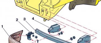
6. Unscrew the screws that secure the instrument panel to the cross member of the front part of the body in accordance with the diagram:
7. Disconnect the fastening nuts: two of them are in the lumen of the glove, and two are in the calibration composition of the device.
8. Remove the instrument panel from the vehicle. Installation is carried out in the reverse order of removal.
as a take off dashboard from a VAZ 2106 car
The dashboard installed on the VAZ 2106 is actually 100 percent similar to the dashboard in which the VAZ 2103 model is installed. Accordingly, the panel removal process is valid for both the VAZ 2103 and the VAZ 2106.
1. Disconnect the negative terminal from the car battery.
2. Use a Phillips screwdriver to loosen the screws holding the glove in place. Then unscrew the bottom panel screws: one on the right and one on the left. We also unscrew the screw on the top panel of the radio panel.
3. Carefully slide the flathead screwdriver out of the radio control panel. Disconnect the buttons and switch the wires.
Removal and installation of the instrument cluster VAZ 2101 Zhiguli
- Repair manuals
- Repair manual for VAZ 2101 (Zhiguli) 1970-1985.
- Removing and installing the instrument cluster
Removed instrument cluster
| 1 – holder The arrows show the sockets of the warning lamps and the instrument cluster lighting lamp (middle at the top). |
| EXECUTION ORDER |
↓ Comments ↓1. Technical data 1.0 Technical data 1.1 Main overall dimensions of the VAZ-2101 car 1.2 Main overall dimensions of the VAZ-21011 car 1.3 Main overall dimensions of the VAZ-2102 car 1.4 Technical characteristics of the cars 1.5 Controls and monitoring devices 1.6 Ignition switch 1.7 Interior ventilation and heating controls 2. Operation and Maintenance 2.0 Operation and maintenance 2.1. Vehicle operation 2.2. Vehicle maintenance 3. Engine 3.0 Engine 3.1 Features of the device 3.2 Possible engine malfunctions, their causes and methods of elimination 3.3 Removing and installing the engine 3.4 Disassembling the engine 3.5 Assembling the engine 3.6 Bench tests of the engine 3.7 Checking the engine on a car 3.8. Cylinder block 3.9. Pistons and connecting rods 3.10. Crankshaft and flywheel 3.11. Cylinder head and valve mechanism 3.12. Camshaft and its drive 3.13. Cooling system 3.14. Lubrication system 4. Fuel system 4.0 Fuel system 4.1. Power system 4.2. Carburetor 5. Ignition system 5.0 Ignition system 5.1 Setting the ignition timing 5.2 Gap between the breaker contacts in the ignition distributor 5.3. Checking ignition devices on a stand 5.4 Possible ignition malfunctions, their causes and methods of elimination 6. Starting and charging system 6.0 Starting and charging system 6.1. Battery 6.2. Generator 6.3. Starter 7. Transmission 7.0 Transmission 7.1. Clutch 7.2. Gearbox 7.3. Cardan transmission 7.4. Rear axle 8. Chassis 8.0 Chassis 8.1. Front suspension 8.2. Rear suspension 8.3. Shock absorbers 8.4 Possible malfunctions of the chassis, their causes and methods of elimination 9. Steering 9.0 Steering 9.1 Features of the device 9.2. Inspection, check and adjustment of steering 9.3. Steering mechanism 9.4. Steering rods and ball joints 9.5. Pendulum arm bracket 9.6 Possible steering malfunctions 10. Brake system 10.0 Brake system 10.1. Features of the device 10.2. Checking and adjusting brakes 10.3. Clutch and brake pedal bracket 10.4. Main cylinder 10.5. Front brakes 10.6. Rear brakes 10.7. Rear brake pressure regulator 10.8. Parking brake 10.9 Possible brake malfunctions, their causes and methods of elimination 11. Electrical equipment 11.0 Electrical equipment 11.1. Electrical circuit diagrams 11.2. Lighting and light signaling 11.3. Sound signals 11.4. Windshield wiper 11.5. Heater electric motor 11.6. Control devices 12. Body 12.0 Body 12.1 Features of the device 12.2. Repair of the body frame 12.3. Paint and varnish coatings 12.4. Anti-corrosion protection of the body 12.5. Doors 12.6. Hood, trunk lid, bumpers 12.7. Body glazing and windshield washer 12.8 Instrument panel 12.8. Removal and installation 12.9. Seats 12.10. Heater 13. Features of repair 13.0 Features of repair 13.1. Car VAZ-21011 13.2 Cars VAZ-21013 13.3. Car VAZ-2102 13.4 Cars VAZ-21021 and VAZ-21023 14. Applications 14.0 Appendices 14.1 Tightening torques for threaded connections 14.2 Tools for repair and maintenance of vehicles 14.3 Used fuels, lubricants and operating fluids 14.4 Basic data for adjustments and control |
How to Remove the Instrument Panel on a VAZ 2101
Replacing the instrument panel on a VAZ 2103, VAZ 2106
Welcome! Dashboard. It occupies a very important place in the car's interior, because if it doesn't, how will you know how fast the car is going, what the engine temperature is, and so on. To replace the instrument panel with a VAZ 2106, read below.
The note! To replace the panel, you will need the following tools: the first pliers and two screwdrivers, and you may need a basic set of wrenches and a marker!
Question? And for what purpose do you change the dashboard in your car? (Write your answer in the comments)
Result:
How to replace the instrument panel on a VAZ 2103, VAZ 2106?
The note! In most cases, replacement panels are not replaced, but only removed to replace devices and switches, so if you only want to replace devices or switches, use the dedicated replacement article called "Replacing Panel Tools"!
Conclusion: 1) First, lift up the screwdriver and remove the five screws that secure the top and bottom of the steering column cover.
The note! The photo below the letter "A" shows the screw that secures the housing to the auxiliary steering switch, and this also needs to be removed, but only carefully!
2) Once all the screws have been removed, remove the lower and then the upper housing from the steering column.
Replacement of the VAZ 2101 instrument panel + work with the heater
(No Ratings Yet) Loading...Despite the fact that the VAZ 2101 is not young, the car is still in demand. However, the standard option seems boring to most car enthusiasts, so it’s time to do a little tuning yourself. Let's turn our attention to the interior, more specifically, the dashboard of the VAZ 2101 and replace this element. Specialized stores offer a wide selection of instrument panels for the VAZ 2101, each of which is characterized by both its advantages and disadvantages. If you take the option from the six, the appearance of the interior will not look the way you would like, in addition to this the poor quality of the heater. Perhaps one of the few advantages of this model is the presence of a tachometer. The instrument panel of the five is the absence of a tachometer, but the presence of a modern heater, and the shape of the panel itself looks better.
The seven's panel is characterized by the best heating system and a tachometer. Of the three panels, you can, of course, install absolutely any one, but I think the instrument panel from the VAZ 2105 is optimal. Moreover, the use of a heating system is a rather rare thing, since a radio tape recorder is often installed instead.
Before starting tuning, we advise you to cover all the seats so as not to get them dirty. Then remove the shield and the glove compartment shelf, unscrew the 4 nuts securing it to the engine compartment. We dismantle the steering column, and only lastly remove the pedal assembly and the lower heater casing. Assembling the stove is carried out according to the attached instructions. There should be no problems with assembling the heater, since it is assembled quite easily. Difficulties may await you when working with sharply bent control cables. To simplify the task, we change the order of control of the heater, that is, the top handle becomes the heater tap, the middle handle becomes the air flow, the bottom handle becomes the heater air damper. The use of a cable seal allows for final sealing.
Installation of the right duct is relatively simple, but the same cannot be said for the left one. In this case, you will have to remove the pedal assembly and steering column. From the instrument panel of the VAZ 2101 we remove all parts that may interfere with the modification process.
We connect the right mounts to the engine shield, the central ones are held in a U-shaped bracket. Before starting work with wiring, decide on the location of the radio and control buttons. It is optimal to have a ready-made electrical circuit.
We independently remove the dashboard of a VAZ 2107
For a novice car enthusiast, removing the dashboard may not seem like a very difficult task. But this impression is deceptive. Before the VAZ 2107 instrument panel is completely removed, you will have to do a lot of manipulations, which we will tell the reader about in this article.
The most common reasons for dismantling
- One or more devices have failed.
- The panel joints began to creak while driving, and the car owner decided to glue them from the inside to eliminate this annoying creak.
- Several light bulbs on the panel burned out.
- The speedometer cable has become unusable and needs urgent replacement.
Required Tools
- Set of open-end wrenches.
- Flat blade screwdriver (medium size).
- Phillips screwdriver (medium size).
- Pliers.
? Speedometer cable for VAZ 2101 cable replacement / minor repairs
Speedometer creaking, stopped showing data? The speedometer works. speedometer cable included in VAZ 2101
requires.
The heater is installed according to the instructions, except that you can leave pennies on the top of the body with the air dam (for me this was a necessary measure because I could not find the air dam 2105, but I do not want to buy an insulation block).
To do this, separate the part of the upper heater housing into which the air duct was inserted. In practice this will become obvious as soon as the furnace 05 is attached to the upper body 01.
Install the heater body with sealant, secure the brackets and insert into the air ducts. A blown glass channel is also assembled for sealant. When connecting the control cables, a problem arises of their very sharp bending (due to the use of the upper housing 01), and is solved as follows:
1) New procedure for controlling the heater: - top handle for controlling the heater; - middle handle. air flow adjustment, side deflectors - bottom handle Heater control.
2) The heater air damper cable is routed through the windshield heated channel (as shown in the photo). To do this, a hole is drilled through it, through which the control cable will pass without kinks. Secure this position of the cable with a gland (2 pieces required).
Having completed this work and connected the control ropes of the furnace to the control unit, we proceed to installing the side channels. The right duct lifts up without issue, and to install the left one you'll need to remove the steering column and pedal box (if you haven't already). If it was impossible to purchase side channel deflector seals, then VAZ 2101 seals can be used.
Important points
- Before removing wires and connectors, it is recommended to mark them to make reassembly easier. It is convenient to apply these marks with a black marker or felt-tip pen (because most of the connectors under the dashboard are white).
- You need to carefully remove the upper part of the steering column protective cover, as you can damage the rubber ring on the ignition switch (it gets caught on the edge of the cover and breaks easily).
- When removing the additional panel, do not tilt the screwdriver too much: the clamps that hold this panel are plastic and break very easily.
As can be seen from this article, removing the dashboard on a VAZ 2107 is a labor-intensive task, but it is doable. The main thing is to adhere to the instructions outlined above and not to use too much effort when removing: the panel material, despite its apparent strength, breaks quite easily.
If you find an error, please select a piece of text and press Ctrl+Enter.
The most common reasons for dismantling
Rules for replacing the dashboard of Audi cars
There are a lot of reasons for removing the tidy on a VAZ 2107, and some of them can be called banal, but nothing can be done. The most common reason when you need to remove the instrument panel is a burnt-out backlight bulb. Replacing light bulbs in the dashboard of a VAZ 2107 is carried out only when dismantling the device, and this procedure is simply impossible to perform otherwise.
The dashboard on the VAZ 2107 must also be removed for a number of the following reasons:
- Malfunction of pointer indicators.
- Failure of the instrument lighting, as well as lack of functionality of the arrow indicators.
- Replacing the device with a new one, for example, if a digital panel is installed instead of the factory instrument panel.
- Tuning or upgrading the device.
As practice shows, most often the need to dismantle the dashboard arises precisely because the backlight bulb burns out. If the device is dismantled for this reason, it is recommended to immediately replace conventional light bulbs with LED ones.
We recommend: Replacing rear brakes with disc brakes on a VAZ 2107
Required Tools
Before starting work, you will need to prepare the necessary tools so that you do not have to be distracted during the process. Despite the fact that the work of removing the device in question is quite labor-intensive, to implement it you will need a small set of tools, including:
- Phillips and slotted screwdriver.
- Electrical tape to indicate chips that are disconnected from the device.
- Work gloves for unscrewing the speedometer cable.
When all the tools are prepared, it remains to make sure that the parts and elements that are planned to be installed or replaced on the dismantled device are available. After this, we proceed to perform the main part of the work.
Instructions for removing the dashboard on a VAZ 2107
Initially, it should be noted that the process of dismantling the tidy on VAZ 2107 cars, the injector and carburetor are identical, therefore the instructions described below are appropriate for sevens of all years of manufacture. Having prepared to carry out the work, you can proceed by following the following sequence:
- First you need to turn off the power to the car, for which you remove the negative terminal from the battery. This must be done, since the work will be carried out in the electrical part, and the likelihood of a short circuit occurring is quite high.
- Next, we move into the interior, and using a slotted screwdriver, we remove three caps from the levers responsible for the operation of the heater.
- Using a slotted screwdriver, remove the plastic plug on which the heating sign is depicted. This plug is on the right, and under it there is a Phillips screw that needs to be unscrewed. (There are 2 screws under the plug, but only one needs to be unscrewed - the top one, which secures the right side of the dashboard).
- Next to the hazard warning button, there is an odometer reset button, which is secured with a plastic nut. The nut must be unscrewed and removed with the washer located behind it. The button is recessed inside the panel.
- The right side of the tidy is weakened at this stage, and it remains to perform several additional manipulations in order to completely dismantle the device. To do this, pull out the right side of the device, thereby freeing access to its rear part. Here you need to disconnect all the chips and wires to perform dismantling.
- Initially, the power chips for the stove button are disconnected. Be sure to remember the location of the wires. It is recommended to take photos so as not to be confused when assembly is carried out.
- Next you need to disconnect the speedometer cable. It is secured with a special nut, which can be unscrewed by hand.
- All chips connected to the dashboard are disconnected. It is almost impossible to confuse their locations, since they have different fastenings and differ in size.
- The supply hose is removed from the economizer fitting. This cable is located on the left side of the device.
- After all the chips, cables and wires are disconnected from the device, you can dismantle it.