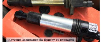
Selecting an ignition coil for VAZ 2106
The design of classic VAZ cars does not place excessive demands on the ignition coil. The coil must meet certain parameters and produce the required voltage. On the VAZ 2106 you can install coils from the following manufacturers:
SOATE offers a complete set of ignition system elements
Usually, VAZ 2106 owners, when purchasing, look for powerful coils at a low price, since the power characteristics of the engine directly depend on the number of turns of the winding. Experienced car owners give the following advice:
The most reliable coils are Bosch - these are powerful, high-quality devices with maximum service life.
Ignition coil device
It is necessary to know the structure of the ignition coil in order to be able to imagine its electrical circuit and why it is needed in the car’s ignition system.
ignition coil B117-A
You have become familiar with the design of the coil. Now let’s compare the structure of the ignition coil with its schematic representation of two windings, for a more visual representation of its structure.
How to check the ignition coil - basic methods
In principle, you can determine the cause yourself, since checking the functionality of the ignition coil is quite simple. To do this you need to remove it. Depending on the car model, you should look for it in the engine area, namely the cylinder block. In order not to harm the electrics, disconnect the negative cable from the battery and the connector on the coil. Next, you need to sketch out on paper exactly how it was installed and, of course, connected. The ones that interest you most are the high-voltage wires; their diagram is extremely important; after sketching it, remove their terminals from the coil.
All that remains is to unscrew four bolts and the part is removed. Then carry out a visual inspection for defects and chips; there should be none. Also clean its body from dirt, because it contributes to the occurrence of large voltage leaks. In order to check the bobbin for breaks, you need to know how to ring the ignition coil; for this you only need an ohmmeter (one of its terminals is connected to the winding input, the second to the output). First ring the primary and then the secondary windings. The resistance on the first should be much lower than on the second.
There is another way to check the ignition coil if the previous methods did not reveal any malfunctions. In this case, it is necessary to connect the primary winding of the bobbin to a DC source (12 V), connecting it to the buttons, they are designed for a current of 20 V. In parallel, connect a capacitor with the same capacitance as in the ignition system. A candle is connected to the second winding, and the source is quickly turned on several times. The resulting crackling indicates the presence of breakdowns. Thus, there is nothing difficult about how to check the serviceability of the ignition coil; the main thing is to monitor its condition, since any malfunctions can lead to very negative consequences. Repair consists of restoring the winding or completely replacing the part; it is inexpensive, fast and reliable.
Home →
Device → Electrical system → Ignition system →
Checking for a spark
If problems with the ignition system overtake you on the road, you can check the presence of a spark (and, consequently, the performance of the coil) without a tester. This method is addressed only to owners of cars that are not equipped with a catalyst, since this part can be seriously damaged during testing.
The check is carried out in several stages:
- We fix the ignition cable on the cylinder head with tape or hold it in pliers that have good insulation. It should be located at a distance of no more than 10 millimeters from the mass;
- we start the engine (for this purpose it is better to invite an assistant, since otherwise you simply will not be able to see the spark);
- We are watching the cable. When the power unit is running, large sparks should appear between it and the ground;
- If this does not happen, you will need to disconnect the plug, turn on the ignition and make sure that sufficient voltage is supplied to the coil.
The second way to check a pulse transformer involves using another coil that is known to be working. If, after installing it, a spark occurs normally, then the old part must be replaced.
Although there are several methods for checking the functionality of the ignition coil without any special equipment, we still strongly recommend using an ohmmeter or multimeter. This equipment will help you obtain accurate resistance readings and draw appropriate conclusions.
Ignition coil VAZ 2106
The VAZ 2106 ignition system includes:
- ignition coil;
- distributor;
- spark plug;
- low voltage wires;
- high voltage wires;
- egnition lock;
- ignition relay.
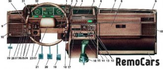
Diagram of the VAZ 2106 ignition system: 1 - generator; 2 - battery; 3 — four-pin connecting block; 4 — ignition coil; 5 — distributor (distributor); 6 — ignition switch; 7 - high voltage wires; 8 - spark plugs
Purpose
The ignition coil is a high-voltage pulse transformer. Its main function is to create a high voltage in the circuit to form a spark. A spark, in turn, is necessary to ignite the fuel-air mixture during operation of an internal combustion engine. If the coil is faulty, the car simply will not be able to start.
The ignition coil is cylindrical in shape
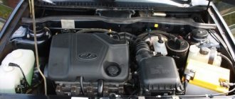
Location
On the VAZ 2106, the ignition coil is installed in the left front corner of the engine compartment. It is fixed to the mudguard with two nuts and can be easily removed if necessary.
The VAZ 2106 ignition coil is mounted in the upper front corner under the windshield frame
Device and connection diagram
The central part of the coil is the core, on which about 30 thousand turns of thin wire of the secondary winding are wound. A layer of thick wire is wound onto the secondary winding - the primary winding. Some ends of both windings are connected to the battery, the other to a distributor that controls the power supply. During the winding process, the thin and thick wire will have points of contact. One of these points must be connected to a voltage switch. In this case, the function of the coil core is reduced to enhancing the magnetic field.
When connecting the coil, it is important to follow the order of connecting the individual wires in accordance with their functions
Ignition coil winding
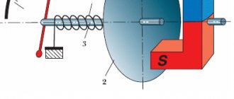
An explanation will be given in the second image of the figure, located on the right side (Fig. 2).
The ignition coil is a static electromagnetic device consisting of a ring magnetic circuit and two windings, which are placed on the core. From this we can conclude that the design of the ignition coil is made in the form of a step-up current transformer.
Now let's look at what the primary and secondary windings of the ignition coil are connected to.
Ignition coil primary winding
As is known, in the electrical circuits of cars, a single-wire system is used to connect the current source (battery) with various consumers, such as:
- ignition system;
- lighting system,
- alarm system
and so on. The second guide is the mass of the car, but this relates to completely different topics that will be published in this section.
The figure shows an image of the battery ignition contact system (Fig. 3). From this diagram it can be understood that the low voltage circuit receives power from the positive terminal of the battery, that is, the primary winding of the ignition coil is connected to the battery (+).
Secondary winding of the ignition coil
The central terminal (9) of the ignition coil is connected to the secondary winding. The high voltage wire from the center terminal of the coil goes to the center electrode with a terminal located in the distributor cover (details will be described in the following topics).
Now, you need to understand how to check the primary and secondary windings of the ignition coil.
Checking the ignition coil
In this way, the resistance for the primary winding of the ignition coil is checked (photo 1). The measuring device (multimeter) must be installed in the position of the resistance measurement range, then connect the wire connectors to the corresponding sockets of the device. One probe of the device is connected to the output terminal of the primary winding, the other probe is connected to the output terminal of the primary and secondary windings. In this example, the device display will indicate a primary winding resistance of 39 ohms.
Using this method of connecting the probes of the device to the coil terminals, you can measure both the total resistance of the two windings and the resistance for the secondary winding (photo 2).
That is, if you connect one probe to the output terminal of the primary winding of the ignition coil (diagram in Fig. 3) and connect the other probe to the central terminal of the ignition coil, the display of the device will indicate the total resistance of the two windings.
The main problems with heating the radio
Overheating of the case can lead to an emergency shutdown of the gadget in order to avoid more serious damage to all devices of the machine. Let's look at all the reasons why the radio in the car gets hot. First of all, it must be said that this process is natural, even when the gadget is turned off.
Car radio
Any car radio always gets warm when listening to music, especially when the sound is loud. Some manufacturers have a cooling system installed on the radio directly from the factory. This is especially necessary for hot countries if the products are intended for sale in such regions.
From this it follows what to do in this case for motorists who are faced with such a situation in their car:
- you need to connect special coolers for the radio;
- Provide ventilation in the front instrument panel shaft.
These are interchangeable solutions; many motorists have encountered them more than once in their lives. If the radio in the car heats up, then we are talking about a natural process with electronic components. Almost all microprocessor-controlled microcircuits overheat. Coolers or coolers are usually installed directly above the processor. The entire board is cooled in the radio.
Car radio
Moreover, the heating ability depends on the production technology. For example, the Pioneer radio of an earlier production gets hot, but now this problem is less pronounced, since the principle of producing microcircuits for mobile terminals is used. Such devices require less cooling. At the same time, prolonged work always leads to an increase in temperature.
Chinese car radio
It is Chinese technology that is more susceptible to temperature increases, but only if cheaper technology is used. When purchasing the same Pioneer car radio, check exactly how the device’s board is cooled and how to organize the cooling process when using it.
Car radio Pioneer
Features of the behavior of a pulse transformer
Pulse transformer designers strive to minimize voltage drop, rise time, and pulse distortion. This is caused by an increase in magnetizing current during the pulse duration.
Power to the device is turned on and off using a switch (or switching device) at an operating frequency and pulse width that provides the required amount of energy input to the power supply. Therefore, the temperature is also controlled. When the transformer is in good condition, electrical isolation between input and output is guaranteed by the design of the device.
Transformers used in direct converter power supplies are more likely to overheat, especially if the power exceeds 500 kW. Signal type pulse transformers deal with low power levels and therefore generate little heat.
There will be no problems with overheating of such devices if you control the following parameters:
- Magnetizing current.
- Load current.
- Voltage drop.
- Recoil voltage.
- Secondary load current.
- Pulse distortion.
What causes ignition coil malfunctions?
It is a coil pulse transformer consisting of two windings: the primary winding, which has a small number of turns of thick wire, and the secondary, consisting of many turns of relatively thin wire. In addition, each bobbin has an additional ignition coil resistance. Therefore, many malfunctions can occur simply due to a break in one of the coil windings, and a short circuit in the bobbin windings is also quite possible.
If the key is turned to the active state, but while the engine is not running, this leads to excessive heating of the insulation of the bobbin windings, and, as a result, it dries out and crumbles. Thus, the wires remain exposed, which contributes to the occurrence of a short circuit. In addition, the silicone from which the ignition coil tips are made is also subject to aging, which contributes to the occurrence of leaks and the engine “troits”.
#3 OFFLINE
Posted 04 February 2009 - 08:56
No.. It flattened you. But I need it.
This is interesting: Who turns off the power in a private home - we explain thoroughly
Signs and causes of ignition coil malfunction
Many people believe that heating the coil during operation is a malfunction. However, it is not. A high voltage current passes through the winding, so the coil may heat up slightly.
Symptoms of a problem
The main signs of a faulty coil are as follows.
- No spark. This is the most common symptom in which it is impossible to start the engine. In this case, the coil must be replaced.
- When starting, the engine starts to run and immediately stalls. This is also caused by a faulty coil.
- The engine runs stably and does not overheat, but fuel consumption increases.
Opening the hood, you can see there is no spark when starting the engine.
There are also a number of indirect signs of coil malfunction, which until a certain time do not affect the performance of the engine, but will appear in the near future:
- Mechanical damage to the coil body, which can be seen with the naked eye.
- Breaks in the coil windings.
- Coil overheating.
In addition, the driver should be wary of the uneven distribution of carbon deposits on the spark plugs, as well as the inability to start the engine the first time. If there is even the slightest doubt about the performance of the ignition coil, it is better to check it immediately, avoiding the possibility of it failing on the road.
Causes of malfunction
Experts identify two reasons why the ignition coil may fail.
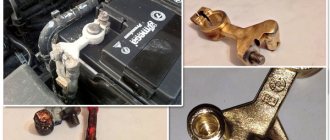
- Using low quality spark plugs. Cheap spark plugs produce reverse gases, which, in turn, can cause breakdowns in insulators. As a result, the coil tips will quickly fail, and you will have to change the coil along with the spark plugs.
- Severe overheating of the coil body. The coil itself must operate in any temperature conditions. However, if the engine overheats frequently, the coil will also experience thermal overload. This usually happens when driving aggressively or there are problems with the engine cooling system.
The quality of the spark plugs directly affects the performance of the ignition coil
. If you eliminate the possibility of these causes, you can significantly increase the service life of the coil.
Ignition coil diagnostics
If you suspect a coil malfunction, you should first check whether voltage is supplied to it. To do this you will need:
- multimeter;
- insulated pliers;
- latex gloves.
You can check the coil with a multimeter both on the car and by removing it from the body
The check itself is carried out as follows:
- The voltage supply to the coil is turned on.
- A multimeter is connected to terminal B+ and ground. It should show 12 V.
- If voltage is not supplied to the coil, then the ignition switch is faulty.
- If voltage is applied, the resistance of the primary and secondary windings is measured. To do this, the multimeter contacts are connected first to the terminals of one winding, and then to the terminals of the other. For the primary winding, a resistance of 3–4 Ohms is considered normal, for the secondary winding – no more than 7–9 Ohms.
The connection is made in turn to each of the coil contacts and to the vehicle ground
Ignition coil: what is it, why is it needed, signs of malfunction
Probably everyone knows that heat engines have spark plugs that ignite the fuel-air mixture. What does the ignition coil do? What is it for?
It is known that in order to produce a spark, a powerful electrical discharge passes through the spark plug, which requires a voltage of more than 15,000 volts. This is precisely what the ignition coil, or simply the coil, provides.
The principle of its operation was invented in the 19th century by the German engineer Heinrich Ruhmkorff. Historically, this is one of the oldest parts in the engine. At the beginning of the twentieth century, it replaced the magneto.
How it works
The ignition coil acts as a flyback transformer. Its functionality is to convert low voltage coming from a battery or generator into high voltage.
See also What to do if the car does not start?
Structurally, the device consists of two coils and an iron core. The coil is a winding of copper wire. Both coils are nested inside each other, with an iron core inside. One coil is called the primary and has relatively few turns.
When the ignition is turned on, the voltage is 12 volts, which corresponds to the voltage of the vehicle's on-board network. Current passes through the coil, creating a magnetic field. To start a spark, the following happens: the current is abruptly turned off, which causes the destruction of the magnetic field. This causes tension in the second, or secondary, bobbin.
It has a significantly higher number of turns than the primary, and the voltage ranges from 15,000 to 30,000 volts.
A mechanical contact, an interrupt contact, was initially responsible for turning the primary current on and off. Its setup was complex; it was necessary to find the optimal distance to the contact so that the time for creating the magnetic field - and therefore the ignition time - was not too short. In addition, the service life of such a contact was relatively short - no more than 15,000 kilometers.
Beginning in the mid-1970s, manufacturers began to use electronics. In the mid-1980s, engineers linked the igniter to the injection system and controlled the process digitally. However, microelectronics only work with small currents, and the ignition coil needs 5 amperes. Thus a new component appeared: the power amplifier. It functions much like an amplifier in a stereo system.
A few years later, the ignition distributor became redundant, and each spark plug received its own ignition coil. This had a number of advantages. The ignition voltage is generated where it is needed, there is no high voltage cable. In addition, the charging time increased and, despite the smaller size, the spark was stronger. These single ignition coils usually also include a power amplifier. For three or four cylinder engines they are often combined into one housing, otherwise they are mounted separately above the spark plug.
Why do they break?
Primarily due to heat and/or vibration. In addition, in older cars with one coil, it was enough to forget to turn off the ignition. At the same time, when the interrupt contact was closed, current constantly flowed through the primary coil and caused heating. So much so that there could be a fire. Today's single coils are mounted directly on the spark plugs, i.e. on the engine. This means that they are also constantly heated and subject to a lot of vibration.
At first, the developers did not sufficiently appreciate the negative capabilities of this load. And in a number of car models, the entire ignition system turned out to be defective. Problems were caused by burnt out limit switches, as well as engine oil. Bad seals leave oil in the spark plug well where it destroys the coil insulation. Another problem can be water, during washing, for example. If high pressure comes into contact with the coil, it can cause a short circuit.
How can you tell if the coil is faulty?
A sure symptom of a malfunction is uneven engine operation, or “triple”. When the engine is running in the dark, “breakdown tracks” appear on the body. Other negative signs include overheating of the structure, the appearance of cracks or chips. In older cars with a single coil, the engine may simply stall. On modern models with single coils this practically does not happen; the engine may run intermittently. But still work.
In a word, if you feel that the engine is very bad, it “stutters”, works jerkily, do not tempt fate. You can’t drive with such a problem! Qualified diagnostics is required. Moreover, it is necessary to find out whether the ignition coil is “to blame”, and not, say, the spark plug. In this case, many of the symptoms are the same.
Is it possible to repair the ignition coil?
In principle, it is possible. Previously, there were even special workshops where the bobbins were rewound again. However, today it is rather exotic. It’s easier and more reliable to buy and install a new one. It's not too expensive.
If you are not strong in electrical engineering, it is best to entrust the installation of a new coil to a service center specialist. Especially if you are the owner of a new car with a custom ignition system. It may cost money, but you will be sure that everything was done correctly and with a guarantee.
Source: https://www.1gai.ru/baza-znaniy/522619-katushka-zazhiganija-chto-jeto-zachem-nuzhna-priznaki-neispravnosti.html
How to properly prevent the cause
Everything can be resolved by qualified routine maintenance, the frequency of which is set by the manufacturer. The main check points are discussed below.
No-load current
Before connecting to the load, the temperature of the housing cover is checked. It cannot be higher than 65...70°C. Otherwise, the insulation coils are inspected. Burnt, darkened or damaged insulation is accompanied by a characteristic burnt odor. The hottest part of the transformer is the coil at the top of the core. If the insulation is damaged or smoke is observed during idle, the device must be urgently tested, and then a decision must be made to repair or replace the unit.
The no-load current should not exceed 2...3% of the total power of the transformer.
When charging
The fault concerns low-power transformers, such as those found in laptop chargers. They convert the voltage supplied from the network into the voltage required by the computer. In this case, the fork overheats. If this overheating is significant and is accompanied by an unpleasant odor, then the charger is replaced; otherwise, subsequent replacement of the computer battery will cause trouble.
You can reduce heat by placing the case on its side or placing a few pencils underneath to improve air circulation. When not in use, the charger is disconnected from the wall outlet.
Short circuit experience
This test is very dangerous, so before starting the test you must make sure that the network load does not exceed the rated power. It is recommended not to conduct the experiment at the maximum operating load on the unit, or on another transformer of a similar model. Fans must operate at maximum speed, and the ambient temperature cannot exceed 25C.
The experiment is not suitable if the transformer is mounted in a closed, unventilated room. Other conditions:
- The branch connections are installed identically;
- The transformer is correctly sized for the harmonic load;
- There are no high currents in the neutral.
Replacing the ignition coil of a VAZ 2106
The ignition coil of the VAZ 2106 is a non-separable device. It cannot be disassembled and repaired. If the coil fails, the assembly is replaced. To do this you will need:
- wrench 8;
- 10mm wrench.
Coil replacement procedure
When replacing the coil, safety precautions must be observed. Since the coil is a high-voltage transformer, before dismantling it, the car must be de-energized by removing the wires from the battery. Further work is performed according to the following scheme:
- Remove the high-voltage wire from the coil body.
- Unscrew the nut from the “OE” terminal of the coil. Then remove the spring washer and wire lug.
- Unscrew the nut from terminal “B+”, remove the washer and tip.
- Unscrew the two nuts securing the coil to the mudguard.
- Remove the failed coil and install a new one in its place.
- Tighten the coil mounting nuts.
- Screw the nut with the wire to terminal “B+”, having previously placed a new spring washer under the tip of the wire.
- Screw the nut to the “OE” terminal, replacing the spring washer.
- Connect a high-voltage wire to the coil body.
Thus, replacing the coil will take 10–15 minutes. Any car enthusiast can easily handle the job.
Video: replacing the ignition coil of a VAZ 2106
Thus, even an inexperienced car enthusiast can check the performance and replace the ignition coil of a VAZ 2106
Particular attention should be paid to observing safety precautions when working with high voltage.
When you can't do without a master
If the power supply has already burned out or is unstable, and the reason is not voltage surges or poor heat dissipation, you need to disconnect the device from the network and call a teleworker. Our specialist will come to the specified address, find out the source of the problem and offer the best solution. Depending on the type of fault, the engineer will replace the failed components (capacitors, power transformer, resistors) or install a new power supply. In some cases, simply replacing the power cord will help.
Please note additionally
Let's consider a few more options why the radio is heating up:
- incorrect connection of wires leads to an increase in temperature;
- Devices in narrow dashboards of cars get very hot; installation can be done in such a way as to free up space;
- The heating temperature increases for those car radios whose interior is covered with dust. It must be removed by opening the case and cleaning.
If you cannot find the cause, contact a specialist who will consistently carry out preventive repairs and determine the cause specifically in your case. Masters usually know what features are inherent in Chinese technology. Where exactly to look for the problem when using devices from different manufacturers. For example, the sound disappears if there are various thermostats on the board that turn off the components of the microcircuit.
Amplifiers for car radios
In general it depends:
- on the characteristics of production (technology used by the manufacturer);
- operating time (whether cleaning is needed);
- release dates (obsolete or new technology);
- from the features of the dashboard;
- on the quality of the installation, for example, on the type of wires and cables, namely what metal they are made of.
Some experts recommend installing speakers in the rear to free up space next to the car radio.
If the device heats up excessively, the problem is of course a faulty connection. First of all, they check the connectors, their quality, and the correct connection of the contacts. To figure out what to do in each specific case, you need to find the overheating point. When the temperature rises strongly, as already mentioned, the car radio turns off or the sound disappears; this triggers the fuses of the device itself or the microphone.
Pioneer radio in the car
Chinese technology has fewer capabilities of this kind. The same budget Pioneer devices will be less protected from such troubles. Why does this particular dependence exist? This is typical not only for “white”, but also for more expensive equipment.
Determining why the ignition coil heats up
The main function of the coil is to convert low voltage voltage, which comes from a generator or battery, into high voltage. There is a generation of high-voltage electrical pulses on the candles. The ignition coil connection diagram provides a certain operating mechanism: when the starter is turned on, thanks to the contact disk, an additional resistance is turned on, this leads to an increase in the current passing through the primary winding, and, as a result, the voltage of the secondary winding increases, which contributes to the reliable ignition of the working mixture.
Malfunctions of the ignition coil can be noticed by the following symptoms. First of all, if it has a high temperature when the engine is off. The cause of this symptom may be turning the key to the active position for a fairly long period with the engine turned off. The next alarming sign is a short circuit, when the engine does not start at all, resulting in a smell of burnt insulation and strong heating of the lock, as well as the starter. In this case, repair and replacement of the ignition coil is necessary.
Dangerous cable: why electrical wires get hot
Heating of electrical wires is a dangerous phenomenon, which can cause the protective insulation to melt and cause the electrical wiring to ignite.
Main reasons for heating:
- The wiring is not installed correctly;
- Poor twisting of wires;
- Poor cable quality;
- Inability of the cable to withstand the load.
In most cases, wires heat up if the cross-section is incorrectly selected. They cannot withstand the modern load of household appliances. It is necessary to limit the number of simultaneous connections of several devices or completely replace the wiring with modern materials.
The cable in the apartment must have a cross-section of at least 2.5 square meters. mm for connecting to sockets, and 1.5 sq. mm for lighting.
If the old wiring was equipped with a copper cable, then the aluminum wire must be connected through special terminal blocks. Aluminum and copper have different electrical conductivities and should not come into contact, otherwise heating of the cable cannot be avoided.
The cable can get hot if it is twisted incorrectly, at the connection points to panels or sockets in the corridor. To fix the problem, it is better to place twists on the terminal blocks.
If the wiring in the house heats up, melts and flares up, you must urgently take the following steps:
- Disconnect the apartment;
- Cut the wire with a tool with wooden handles;
- Cover the flame with a rag.
If you are unable to extinguish the flame yourself, immediately call the fire department.
What causes ignition coil malfunctions?
It is a coil pulse transformer consisting of two windings: the primary winding, which has a small number of turns of thick wire, and the secondary, consisting of many turns of relatively thin wire. In addition, each bobbin has an additional ignition coil resistance. Therefore, many malfunctions can occur simply due to a break in one of the coil windings, and a short circuit in the bobbin windings is also quite possible.
If the key is turned to the active state, but while the engine is not running, this leads to excessive heating of the insulation of the bobbin windings, and, as a result, it dries out and crumbles. Thus, the wires remain exposed, which contributes to the occurrence of a short circuit. In addition, the silicone from which the ignition coil tips are made is also subject to aging, which contributes to the occurrence of leaks and the engine “troits”.
Main reasons
Overheating is assessed in terms of likelihood, frequency and complexity of detection location. Let's look at situations that occur more often.
Short-circuited turn
Mechanical failure, manifested in the following cases:
- Winding error. Distribution transformers have two windings – primary and secondary. High voltage (and therefore low current) is found on the primary winding. From there, they are converted by electromagnetic induction into a reduced voltage and increased current in the secondary winding. During this transformation, the windings are repeatedly subjected to dielectric, thermal and mechanical stress. As a result, damage to the windings is likely, which consists of a violation of integrity or even partial burnout;
- Insulation failure. More often found in places where the winding is bent or turned to the next turn. Occurs when the actual current and voltage values exceed the maximum permissible values (this limit is indicated by the manufacturer in the accompanying documentation). In the event of insulation destruction (for example, during a lightning strike), a breakdown of the winding and a short circuit is observed. Despite the short duration of this process, overheating is significant.
Insufficient load
If there is insufficient load in the secondary circuit, the input voltage does not decrease. Because of this, dielectric leaks are possible, leading to overheating. The cause is easily discovered because an underloaded transformer changes the audible tone of operation.
Overload
The winding material is copper wire, characterized by insignificant heat losses. However, with irregular maintenance, individual parts of the windings overheat. If the device periodically operates at elevated performance values, then over time there is wear and deterioration in the quality of the surface insulation layer. The windings are subject to thermal distortion, which causes the windings to become loose or misaligned. The transformer loses performance, and the temperature on the surface of the windings (with poor ventilation) rises sharply.
Overload can also be caused by:
- Unit vibrations;
- Sudden power surge;
- Gradually accumulating corrosion processes.
Cores
Failure of cores is associated with poor-quality assembly, and therefore rarely becomes a cause of failure. The cores are laminated to avoid eddy currents that cause overheating. The quality of the lamination layer deteriorates sharply if it is not controlled. Overheating begins at the surface, spreading deeper until it reaches the windings. Next, the oil overheats, which evaporates and damages the remaining components of the unit.
Mechanical failure of the core is also possible, which occurs when water gets inside (which subsequently evaporates rapidly) and due to the natural aging of the part material. The risk of overheating is eliminated by changing the transformer oil.
Grounding bushings
Structurally, they are insulating devices that prevent high voltage from entering the conductor when moving to the grounding node. The inside of the transformer uses paper insulators that are surrounded by oil to provide additional insulation. A breakdown in the sleeve sleeve occurs over time and causes overheating.
Control automation and cooling system
The main part of such a system is a thermal relay, with the help of which the voltage level and range are changed. In this case, individual parts of the windings are switched on/off and possible overheating is prevented. The first sign of a thermal relay malfunction is considered to be untimely execution of commands to change the numerical values of the characteristics of the secondary circuit. The relay actuator spring, the material of which has lost its elasticity due to prolonged use, must be immediately replaced. Therefore, the oil cooling flow is not switched on.
Cooling fans, oil pumps and water-cooled heat exchangers must be inspected.
Blog about UAZ
If, when there are interruptions in operation, impossibility of starting, etc., of the UAZ-469B engine, there is a suspicion of a malfunction of the ignition system, then, first of all, it is necessary to check the presence of a spark in the spark plugs.
At the same time, if between the spark plug wires and the engine housing and the high voltage wire of the ignition coil and the housing, a spark breaks through a spark gap of 6-7 mm without interruption, then the ignition system is working.
Checking the operation of the ignition system on the UAZ-469B.
If there is no spark between the high voltage wire of the ignition coil and the housing, you need to check the low voltage circuit between the battery and the ignition coil. This can be done with a portable lamp, using it as a control lamp.
If, when switched on between terminal VK-B of the ignition coil and the car body, the light comes on when the ignition is on, then the low voltage circuit is operational. If the light does not light up, you need to check the ignition switch, ammeter and wiring by connecting one wire of the test lamp in series to the ammeter terminals and the AM and KZ terminals of the ignition switch, leaving the second contact of the light bulb connected to the car body.
If the low voltage circuit between the battery and the ignition coil is working, damage should be looked for in the wires connecting the breaker lever with a contact isolated from the breaker body and the movable and fixed panels in the distributor. Breakage of these wires, as a rule, occurs after prolonged use. This malfunction can be identified using the same portable lamp.
To do this, you need to connect one of the legs of the portable lamp plug with a separate wire to the low voltage terminal on the distributor, and the second leg to the car body. Then turn on the ignition and, turning the crankshaft with the starting handle, observe the lamp. When the contacts are opened, the lamp should light up and vice versa. If the lamp does not go out when the contacts are closed, this confirms a break in one of the indicated wires. In this case, it is necessary to remove the distributor from the engine and eliminate the malfunction.
If the low voltage circuit turns out to be serviceable, it is necessary to check the condition of the breaker contacts and, if there is a malfunction, eliminate it. Interruptions in the operation of all spark plugs of the UAZ-469B engine can be caused by wear on the edges of the breaker cam, a reduced or increased gap between the breaker contacts. As well as a break in the wire connecting the movable and stationary plates of the breaker, short circuit of the primary or secondary windings of the ignition coil, a crack in the distributor cap, wear of the distributor cap carbon and a decrease in the capacitance of the capacitor.
Interruptions in engine operation at high crankshaft speeds may be the result of low pressure on the breaker contacts, which is provided by the spring of the moving contact lever. When the tension of the breaker spring is weakened, the force is less than 500 gf, vibration of the contacts occurs, which leads to interruptions in the operation of the ignition system.
If the spark is weak on all spark plugs, then it is necessary to check the fastening of the capacitor to the distributor body. In addition, a weak spark on the spark plugs may occur if, when starting the engine, the starter does not turn off the additional resistor of the ignition coil. This usually occurs as a result of oxidation of the contacts of the starter switch and slip ring.
Checking the technical condition of the UAZ-469B ignition system devices and their repair.
Speaker repair and subsequent assembly
We install the restored diffuser into the loudspeaker basket, and the terminals of the acoustic wiring must coincide with the terminals on which they are attached. Now you need to determine the polarity of the speaker. To do this, take a 1.5v battery and connect it to the terminals of the dynamic head.
If at the same time the diffuser moves outward, then this connection is correct, and if it is drawn inward, then this is reverse polarity. Thus, you will determine which terminal of the speaker is “+”, and then we solder it to the terminal with the corresponding designation on the basket.
In order to maintain the original length of the supply wires, which were shortened during repairs, now they need to be soldered not by inserting the wire into the hole on the plate, but directly to the terminal, so that there is no tension.
At this step, you need to center the coil relative to the magnetic gap using wedges made of thin electrical cardboard or photographic film, which establish a gap between the coil and the core. In this case, one non-applicable condition must be strictly observed - when placing the wedges in the gap, absolute symmetry with respect to 3 points must be ensured.
Speaker repair. Centering the coil using wedges
Using the example of a dynamic emitter 25GDN-1-4, 4 wedges made of thin cardboard, installed in two pairs opposite each other, are sufficient. The length of such a wedge is selected in this way; If you put the speaker on the table with the diffuser down and the wedges do not interfere, then everything is fine. Next we glue the diffuser.
In my case, I did this: I pushed the speaker membrane up about 15 mm, so that the centering washer did not rest on the basket, then I took a small brush and applied glue to it and the basket. He waited a little, and then moved the diffuser inside and carefully pressed the washer against the basket with his fingers along the entire circumference. Next, in the extended position, I place the diffuser on the glue, while making sure that it does not warp.
After that, I turned the speaker over, put a weight on top and left it for about three hours so that the glue would completely set.
"Hot" alignment
After all the steps have been completed, you need to check the loudspeaker for correct assembly. The check is quite simple, just lightly press the membrane from above and listen to the stroke of the piston. In this case, its movement should be easy, without any grinding.
Now it's time to check the loudspeaker for sound. We connect it to the output of the amplifier and apply a weak low-frequency signal, while there should be no extraneous sounds, only a low-frequency tone. After this, install the dust cap in place.
At this final stage, you need to leave the restored speaker for about a day so that all the glued parts adhere securely. And only after this the finished loudspeaker can be installed in its rightful place. In this way, you can personally repair a damaged dynamic emitter, which was already a candidate for a landfill.
What to do if the loudspeaker makes wheezing noises?
DIY speaker repair No tags for this post.